 |
LagondaNet
|
| View previous topic :: View next topic |
| Author |
Message |
jonc
Joined: 21 Sep 2010
Posts: 584
Location: Cheshire, UK
|
 Posted: Fri Sep 25, 2015 10:52 am Post subject: Components and operation of the aircon / heating system Posted: Fri Sep 25, 2015 10:52 am Post subject: Components and operation of the aircon / heating system |
 |
|
I am preparing to return 13008 to the original aircon/heating system and so have been doing some research into it. I thought I would put it here while I can still remember. This will take a few posts so bear with me..
As we now know, the system is AC Delco and was originally fitted to Cadillacs (see here for more info: http://lagondanet.com/bb/viewtopic.php?t=427)
The control system basically consists of two parts - the Controller and Programmer. The Controller is the slider part with temperature setting knob, the programmer is the black plastic box hidden behind the dash. The two parts are connected together electrically and also with vacuum tubes.
Here is the controller. I have seen three different versions of it - they have slightly different slider knobs. Two have the same width of metal for the slider, one is thinner.
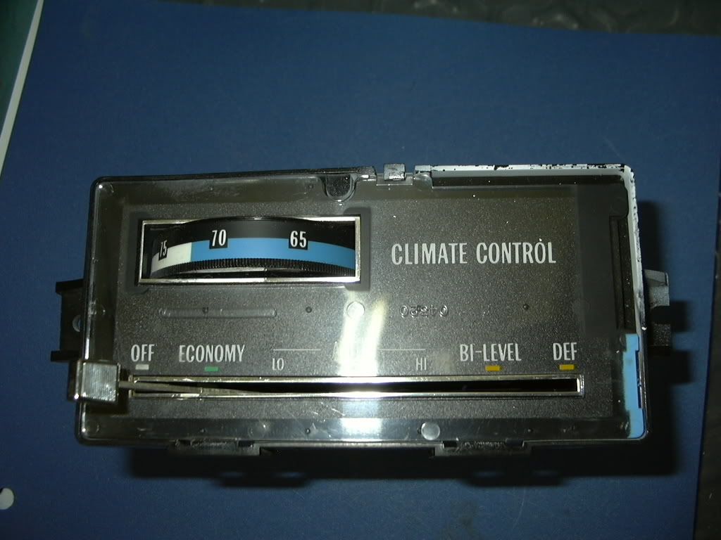
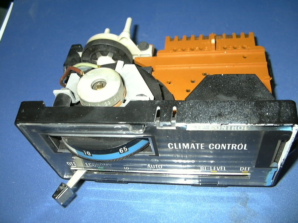
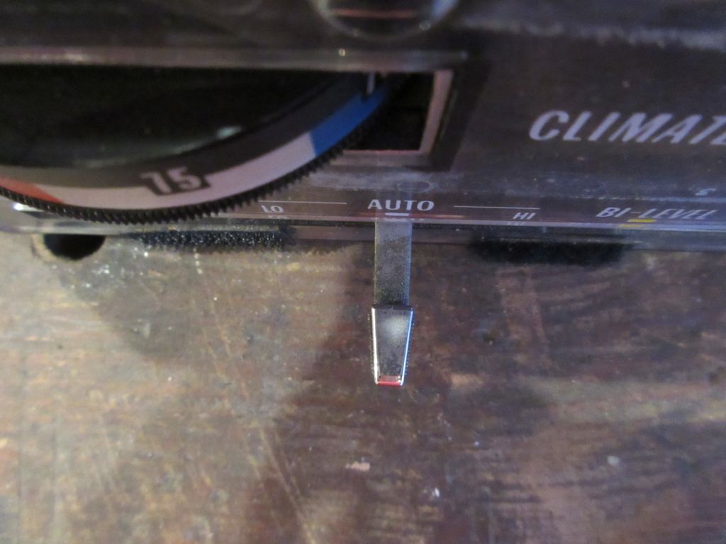
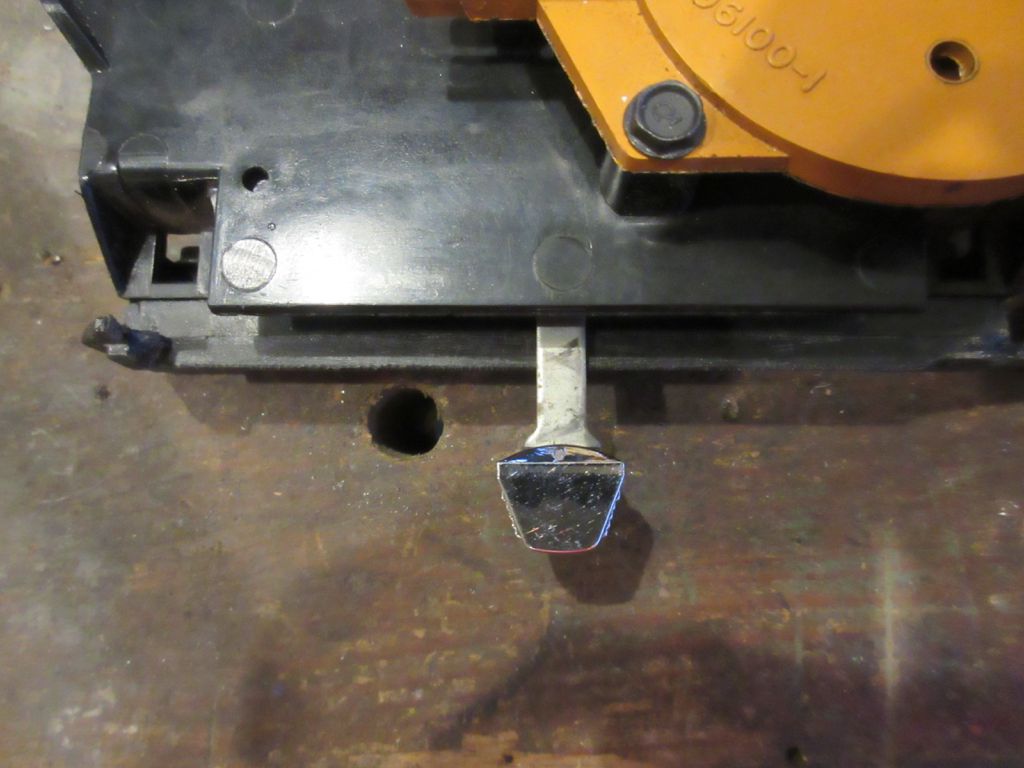
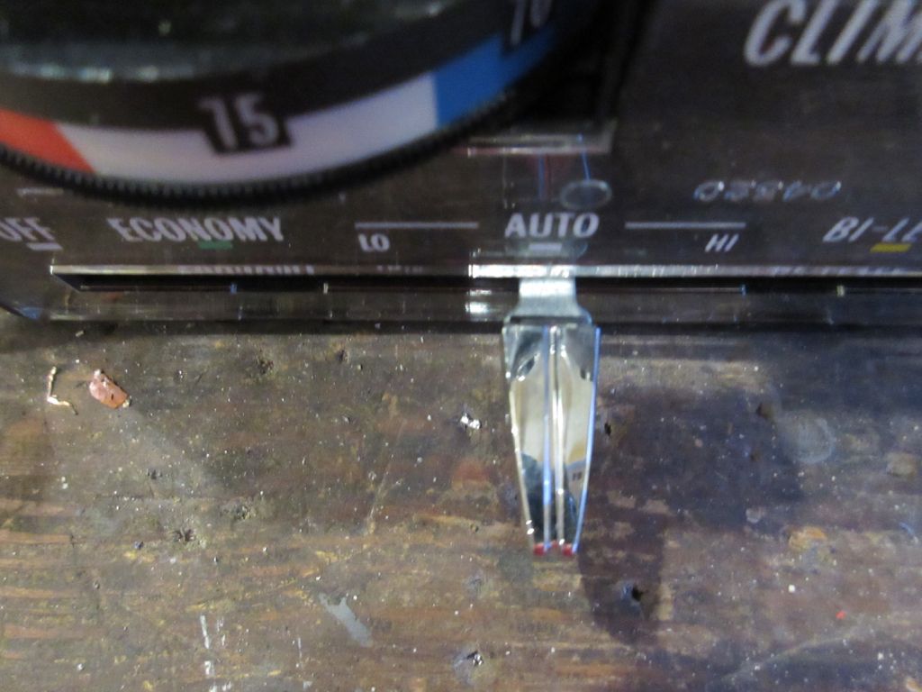
The knob on the two with the thicker lever is interchangeable, so you don't have to use the long, different style one.
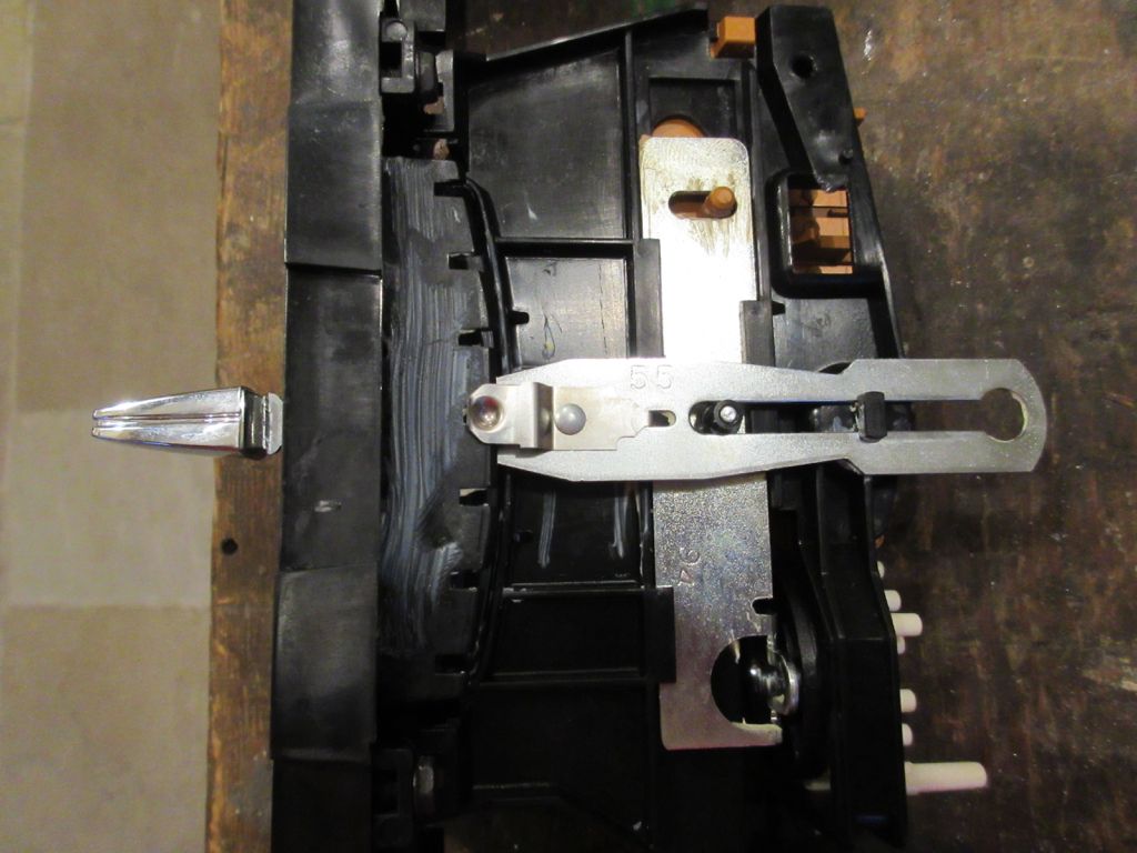
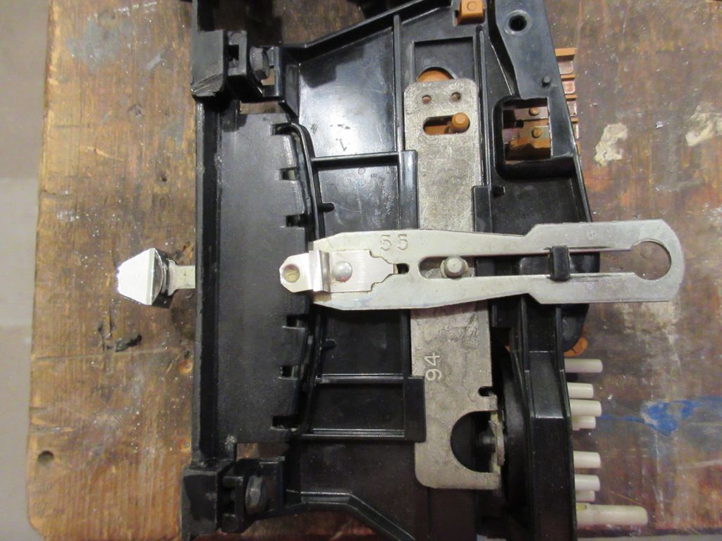
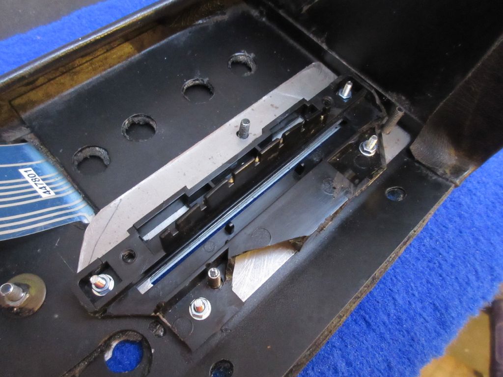
A replacement Controller, whether bought from AML or a breakers yard must be modified. This involves cutting down the front face so that it can be mounted behind the binnacle. This cutting results in a very weak mounting and so on the two occasions I have done this, I have fixed what is left of the plastic to a metal plate which makes the mounting much more secure.
Before chopping:
After:
With metal plate, which allows it to be bolted to the two studs meant for it, plus an additional one which fixes the touch switch plate. This is a later slider with a slightly different plastic moulding:
The Controller also includes the rotary control for the temperature, and the high-temp switch which enables the system immediately if the cabin is hot (instead of waiting for the engine to warm up):
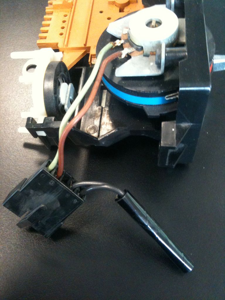
The potentiometer is removed from its metal bracket:
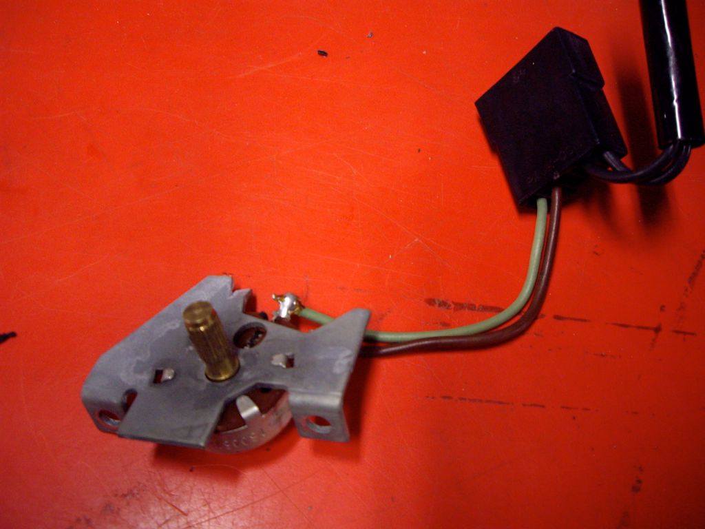
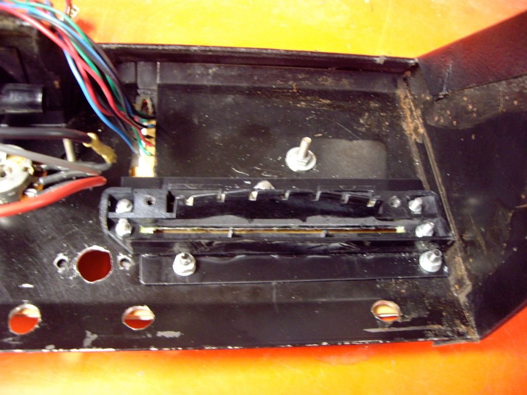
and is held in place by its two lugs through two holes in the binnacle. These lugs are then sandwiched in place by the binnacle membrane plate.
Last edited by jonc on Thu Dec 31, 2015 4:26 pm; edited 2 times in total |
|
| Back to top |
|
 |
jonc
Joined: 21 Sep 2010
Posts: 584
Location: Cheshire, UK
|
 Posted: Fri Sep 25, 2015 11:04 am Post subject: Posted: Fri Sep 25, 2015 11:04 am Post subject: |
 |
|
The other main component, the Programmer is also AC Delco for GM. There are two very similar programmers, but ours is the one on the left, which has the 'trumpet':
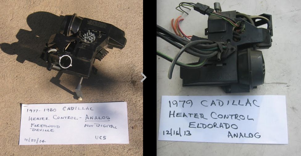
The trumpet part has a thermistor inside it which is used to measure the incoming ambient air temperature.
When the Controller and Programmer were fitted to the Cadillacs, the vacuum pipes were connected together with a vacuum loom:
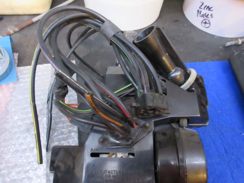
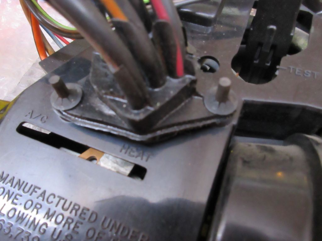
There was a multi-plug on each end, and the two pegs were used to secure it in place. The loom connections are different to the Lagonda and the loom is shorter.
The lid lifts off easily. Here is the inside:
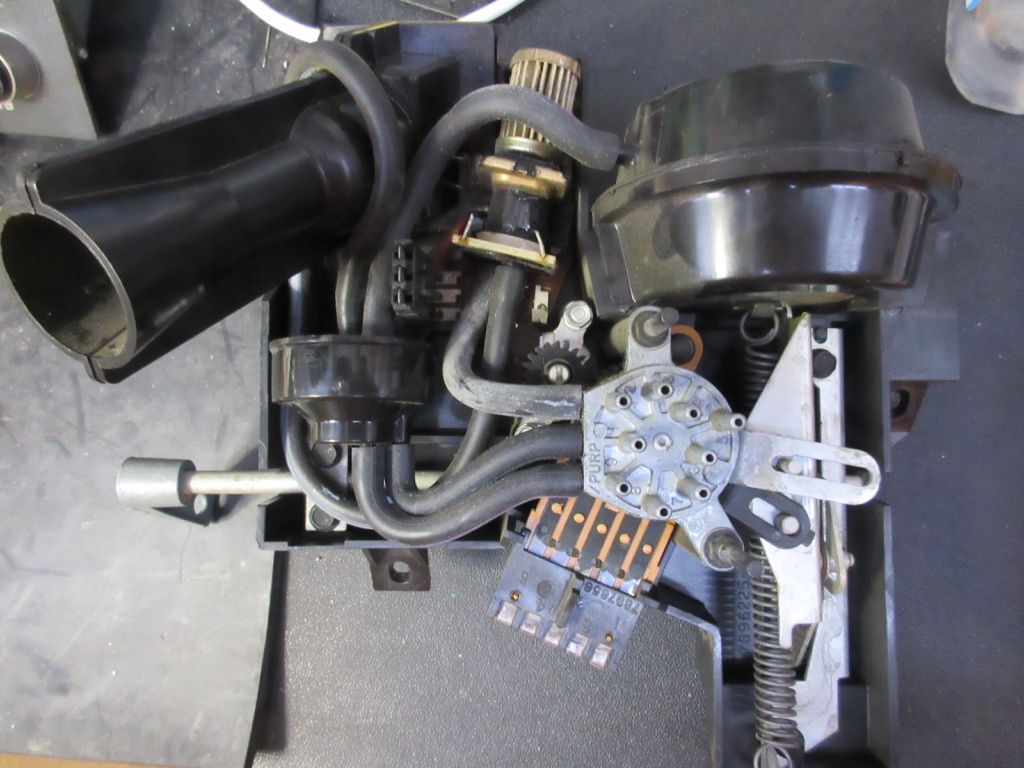
At the top right is the servo diaphragm which pulls against a strong spring. This operates the vacuum switch which rotates anti-clockwise along with the rotary electrical switch below it, and also the output shaft which controls the blend flap on the heater box in the middle of the car. On the left is a vacuum relay and above a circuit board which has a vacuum modulator (with air filter) and also a potentiometer with black cog which senses the rotation.
The rest position is full-cold.
Last edited by jonc on Mon Sep 28, 2015 1:52 pm; edited 1 time in total |
|
| Back to top |
|
 |
jonc
Joined: 21 Sep 2010
Posts: 584
Location: Cheshire, UK
|
 Posted: Mon Sep 28, 2015 1:29 pm Post subject: Posted: Mon Sep 28, 2015 1:29 pm Post subject: |
 |
|
Now on to the system operation. The system has to do these things:
* Decide which vents and flaps to open/close.
* Decide when the aircon pump should run.
* Decide the fan speed
* Decide when to send hot water to the heater.
Note that this system has nothing to do with the rear aircon (when fitted). That only cools when the aircon pump is operating for the front system and has a separate fan switch.
The flaps and water valve are vacuum operated and the blower fan and aircon pump clutch are electric.
Like the Programmer, the Controller (slider switch) operates a rotary vacuum switch and electric switch. In addition, there is a microswitch which AML added, and is only switched in the demist position to control single a vacuum solenoid to open the demist flap.
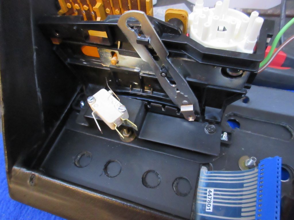
The rotary electric switch here controls the fan speed allowing low, high, or control via the programmer (in auto mode), whether the aircon is operational by enabling the aircon pump clutch power. In demist mode, it also enables the system where it would usually be off (engine temp too low and cabin not too hot) and puts the blower fan on full.
There is one other control, the blue push-switch which is fitted to all but the first 50 or so cars. This is basically a rapid cooling function - it sets the coldest temperature and operates vacuum solenoids to change the vents, and (presumably) set the system to recirculate cabin air.
The vacuum solenoids are mounted next to the Programmer on early cars (round solenoids), and behind the dash knee panel on later cars (square solenoids). |
|
| Back to top |
|
 |
jonc
Joined: 21 Sep 2010
Posts: 584
Location: Cheshire, UK
|
 Posted: Thu Nov 05, 2015 3:25 pm Post subject: Posted: Thu Nov 05, 2015 3:25 pm Post subject: |
 |
|
The best information on the system from AML is the training manual 'Lagonda Air Conditioning Operation and Fault Diagnosis'. There is a description of the system, electrical and vacuum diagrams, and fault diagnosis.
Here are the vacuum diagrams:

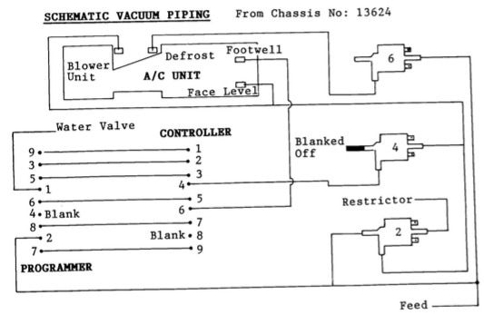
There is an obvious mistake on the top one though - both the inputs of solenoid 6 are connected to the vacuum supply. I think it should be as the second diagram. Also, these apply to cars with the blue button - the top solenoid is operated by it.
It is interesting to see from the later diagram that it took AML until 1989 to realise they could dispense with one solenoid and use output 6 from the controller to operate the footwell flaps!
If you look at the top solenoid (6) on the second diagram, you can tell the way they operate. Here the flap actuator is connected to the bottom port and the vacuum the right one. In one state of the solenoid, the actuator connects to the vacuum (right) and the other, atmosphere (left) - so one way the flap gets vacuum, the other none. In this case, in the off position vacuum gets to the flap actuator and keeps the flaps closed, stopping the air for windscreen demist.
This is the later (3-port square) solenoid valve, as used in the above diagrams:
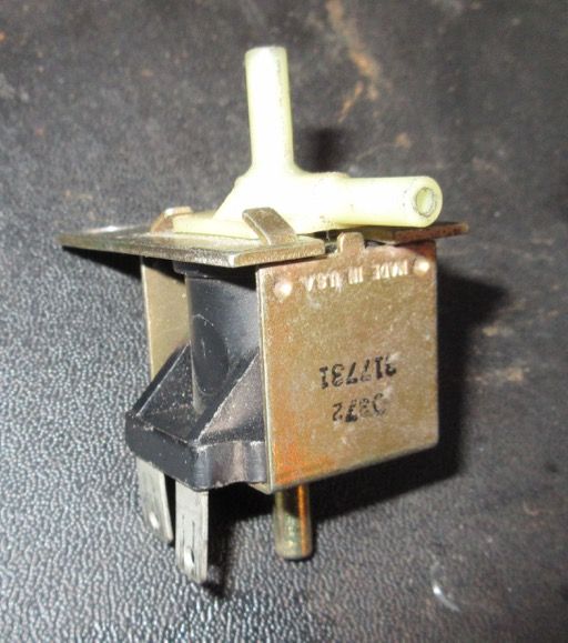 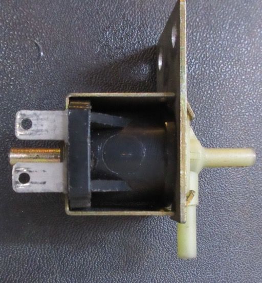
And this is how it operates:
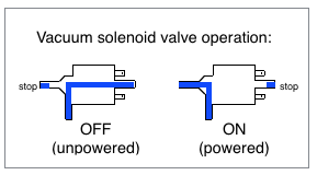
Using this information you can see how the face level and recirculate (blower) flaps are operated by solenoids 2 and 4. In one state they both have the input (bottom port) connected to the right port. Solenoid 4 connects the vacuum supply from the control head to the flap diaphragms and solenoid 2 connects the vacuum to a restrictor. In this state, the flap operation is controlled by the programmer and controller. In the other (left) state, the flaps are connected to the incoming vacuum supply directly which will giving face vents and full recirculate regardless of what the programmer and controller think (an override).
The function of the restrictor is not obvious here, but from studying the Cadillac instructions I can tell you it is there to create a delay. The restrictor causes the vacuum to build up slowly which causes a delay in the operation of the face level and blower flap actuators.
One important note now - THE AML VACUUM DIAGRAMS ARE WRONG.
Having bench-tested this setup, I can tell it is fundamentally wrong. Think of the vacuum functioning of the system like this:
* Programmer vacuum valve: water heat valve on/off, vents open/closed, fresh/recirc air
* Control head vacuum valve: water valve operation yes/no, vents mode.
Now, thinking of a single actuator (operating a vent for example) either it gets vacuum, or it is open to the atmosphere. Important point: both rotary vacuum valves have ports which vent to atmosphere which is needed to kill the vacuum from an actuator; this type of port should only ever be connected to an actuator. The problem with the vacuum diagram above is that in a high-heat condition of the Programmer, the plumbing dumps the system vacuum to atmosphere via port 8 on the Programmer. This has the effect of locking the whole system in high-heat because the vacuum relay inside the Programmer shuts off. That tells me its definitely wrong.
So, where does this leave us? Well, before I get on to that, lets understand how the electrics work.
Last edited by jonc on Wed Nov 11, 2015 9:14 am; edited 1 time in total |
|
| Back to top |
|
 |
jonc
Joined: 21 Sep 2010
Posts: 584
Location: Cheshire, UK
|
 Posted: Fri Nov 06, 2015 11:25 am Post subject: Posted: Fri Nov 06, 2015 11:25 am Post subject: |
 |
|
Here is the electrical diagram, also from the training manual:
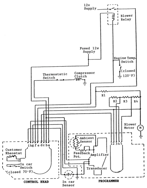
Some important notes: This is a circuit diagram, not a wiring schematic - it doesn't show where the loom goes, where loom plugs are etc. It is also missing the circuits for the solenoids and the blue switch.
The wiring inside the car is a custom AML loom 'AC Loom' which uses the Cadillac plugs but different wire colours. The blower fan, its resistor network, the programmer, control head and solenoids and in-car sensor are all connected on this loom which is basically the bottom half of the diagram. The wiring is slightly different to the Cadillacs because the Lagonda always has a low fan speed (as long as the engine is warmed up) via resistor R1, even when the slider is in the Off position. (On the Cadillac, Off means no fan.)
Looking at the programmer, there are two independent electrical parts - the blower switch (connections 1-5) and the temperature control with its three connections on a separate connector.
It is possible to independently test these two parts.
Here is the blower switch inside the programmer:
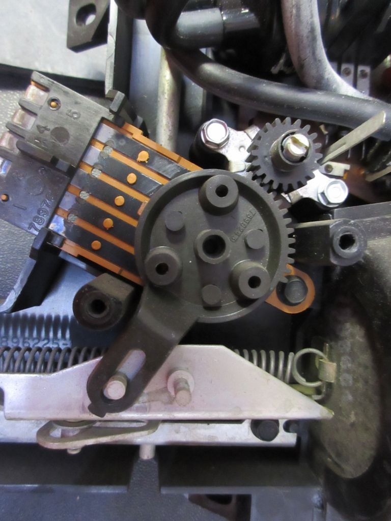
As the vacuum diaphragm pulls to the right, it rotates anti-clockwise. It is shown here in its rest position which is full-cold. Fully anti-clockwise would be full-hot which is close to 90 degrees rotation. Auto on the Controller slider means auto fan speed, and in this mode the fan is controlled using this rotary switch and the fan resistors to vary its speed. In Low or High mode it is over-ridden. You can also see here that there is a cog-drive on it which operates a feedback sensor for the electronics which control the vacuum diaphragm position.
In full-cold or full-hot, the fan speed is highest (12V with no resistors to slow it down). Towards the middle the fan slows down - as the temperature required is getting closer, less heating or cooling is needed.
Now on to the temperature control.
The system senses cabin temperature, regulates for the incoming air temperature, and then sets a vacuum level to position the programmer which then operates the water heater valve, air blend flap in the central heater box and the fan speed switch as already discussed.
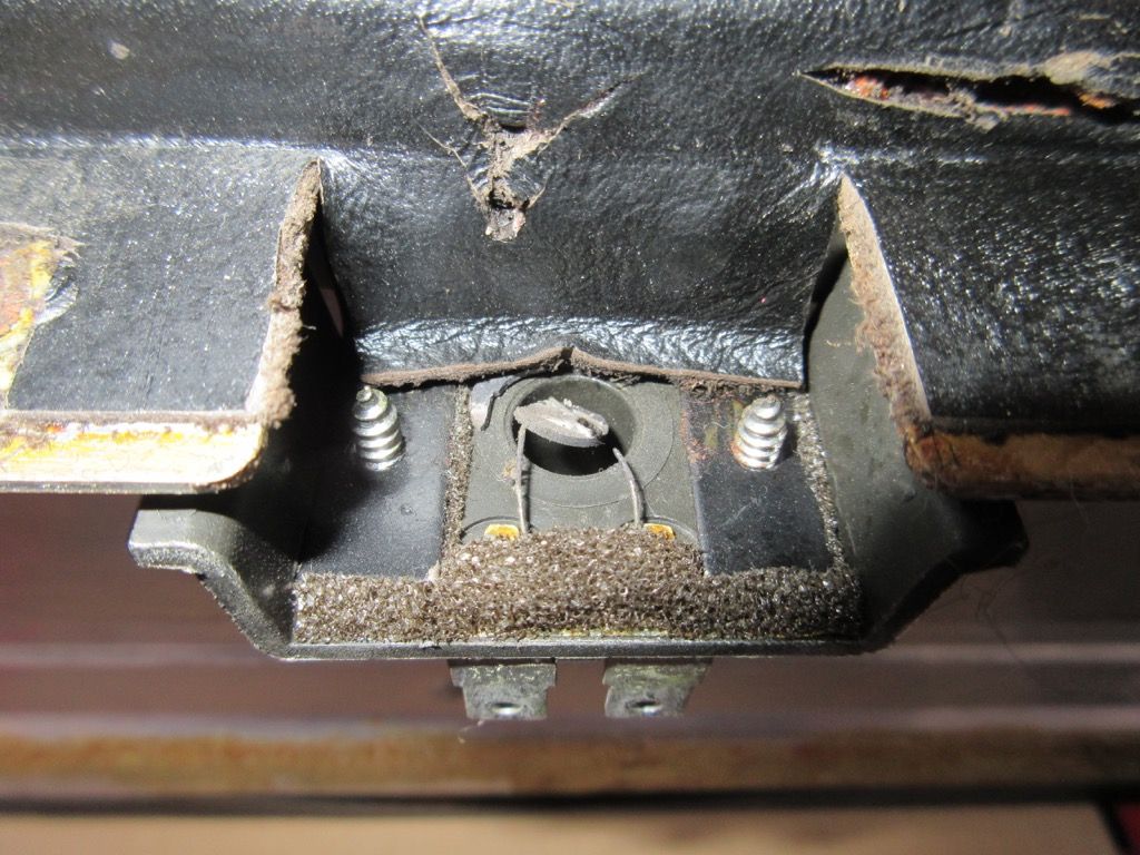
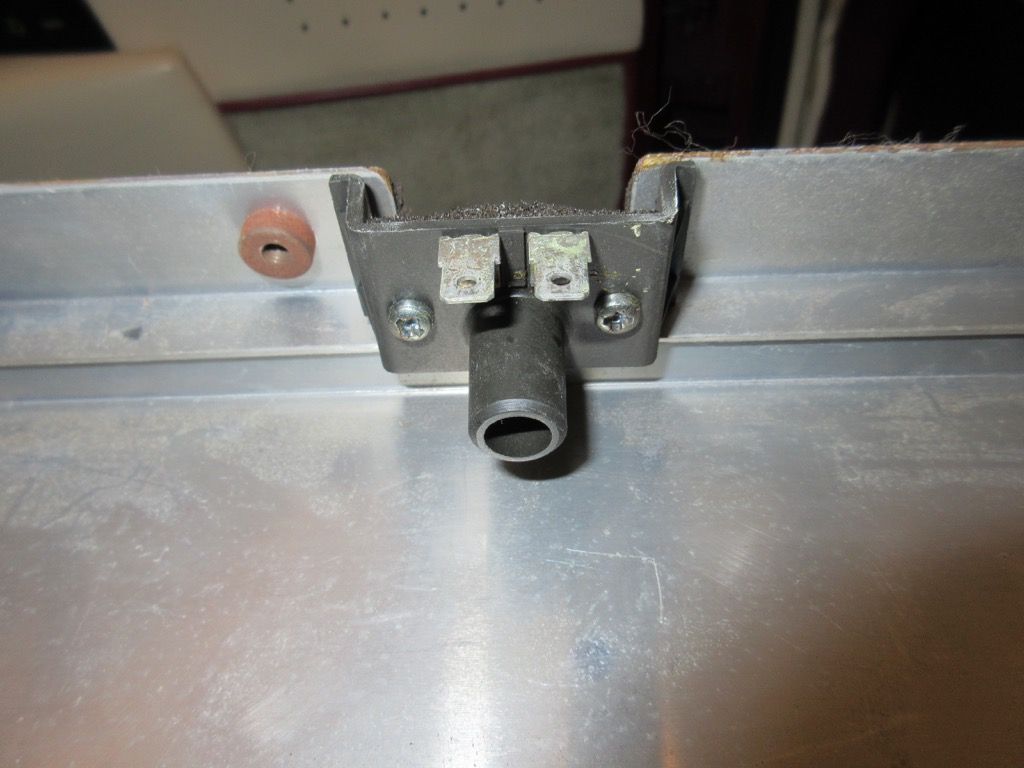
The sensor for the cabin temperature is mounted behind the dash. On LED cars it is behind a small slot at the top of the wood on the passenger side of the dash. Air is drawn from the cabin over it by an aspirator hose fitted to its rear. The sensor is a thermistor and it is in a plastic mounting which appears to be a cut-down Cadillac part:
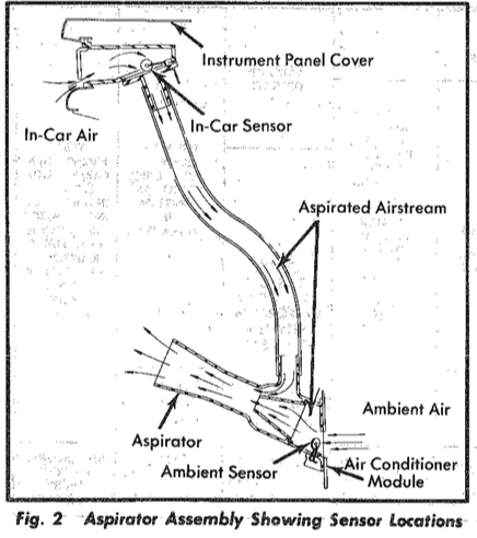
The other end of the aspirator hose connects to the side of the 'trumpet' on the Programmer. The trumpet is fed at the base from another hose which connects to the blower box, providing positive air pressure. This shows the pipes with the Programer removed:
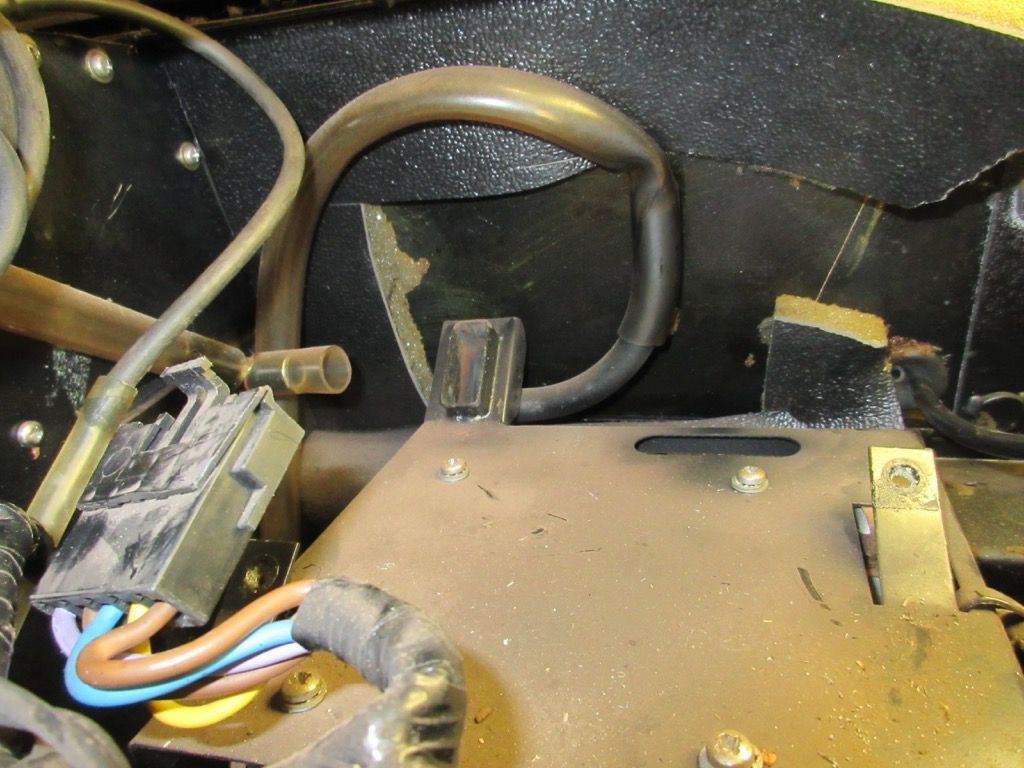
The curvy hose (with the kink) is the one from the blower, which is connected to the rectangular port which mates to the base of the programmer. The best way to show how it works, is to use the diagram from GM:
The GM manual also shows the characteristics of the two thermistors which is potentially useful for finding replacements:
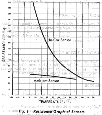
So this says about 75 ohms at 25 degrees C. My bench testing of the programmer and calculations said more like 50 ohms on the programmer I tested, so potentially there may need to be some adjustment here (or I have degraded components in the programmer). |
|
| Back to top |
|
 |
jonc
Joined: 21 Sep 2010
Posts: 584
Location: Cheshire, UK
|
 Posted: Wed Nov 11, 2015 10:33 am Post subject: Posted: Wed Nov 11, 2015 10:33 am Post subject: |
 |
|
So the cabin temperature is sensed by the in-car sensor located just behind the dash which has air passing over it drawn by the aspirator hose.
The electrical diagram looks like this:
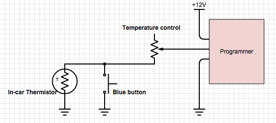
The rotary temperature control on the binnacle increases the resistance of the sensing circuit as it is rotated clockwise, decreasing it as it is rotated anti-clockwise. The thermistor is a negative temperature coefficient (NTC) meaning that as the cabin temperature rises, its resistance decreases.
Basically:
- higher resistance input to programmer = heat mode
- lower resistance input to programmer = cool mode
When the blue button is pressed, this shorts out the thermistor to ground. Oddly, this is arrangement means that the temperature control can still have an effect. For this reason, the AML instructions tell you to have the temperature control in the mid position in order that the programmer receives a low enough resistance for cooling to take place.
The rotary temperature control also has another odd characteristic. It goes open-circuit part way round. This did not happen when installed in the Cadillac because of the constraints of the mounting. I took some measurements:
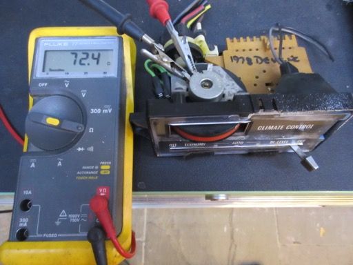 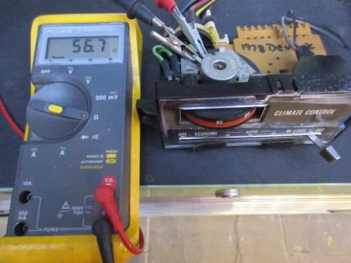
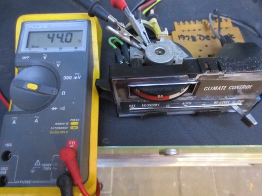 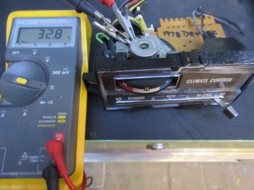
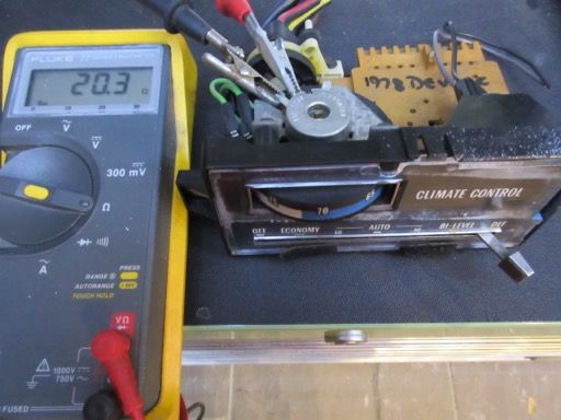 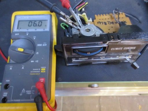
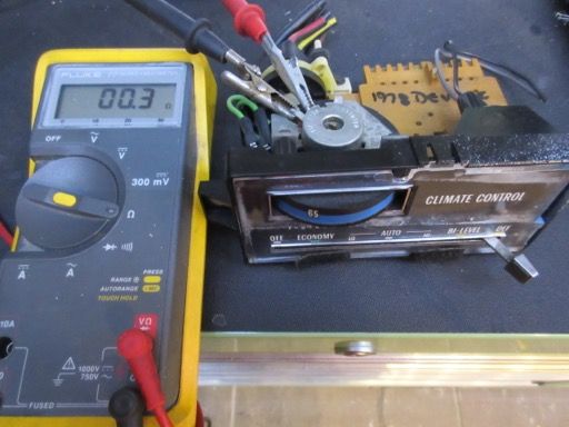
You can see from this that the minimum (full cold) is about zero, the mid position (75 F) is about 33 ohms and full hot is about 72 ohms.
Now look at it as installed in the Lagonda where full movement of the control is allowed. I put an arrow on top to show the rotation:
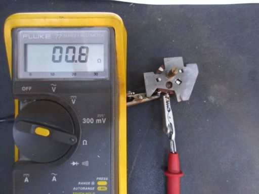 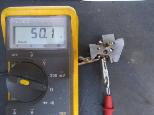
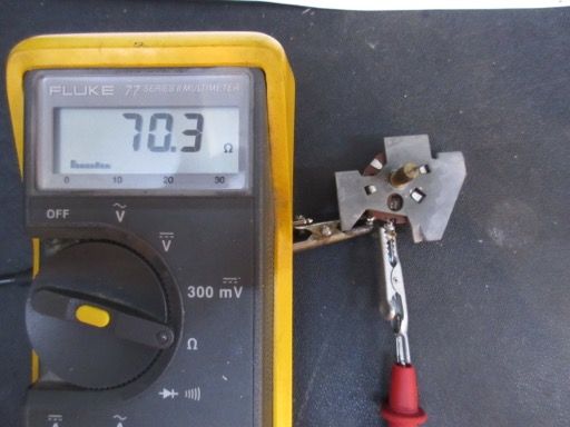 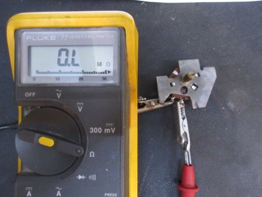
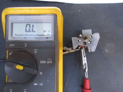
If fully anti-clockwise is 7 o'clock, full heat is reached at about 2 o'clock. This puts the mid, 75F position at between 10 and 11 o'clock. Not as shown on the binnacle legend - basically, anywhere in the red is full-heat.
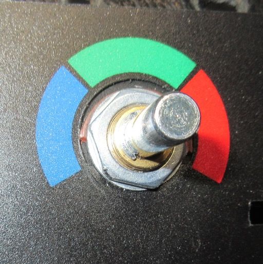 |
|
| Back to top |
|
 |
jonc
Joined: 21 Sep 2010
Posts: 584
Location: Cheshire, UK
|
 Posted: Wed Jan 06, 2016 10:02 am Post subject: Posted: Wed Jan 06, 2016 10:02 am Post subject: |
 |
|
Here you can just see the circuit board of the Controller with its 3-pin connector, and the ambient temperature thermistor poking into the base of the trumpet.
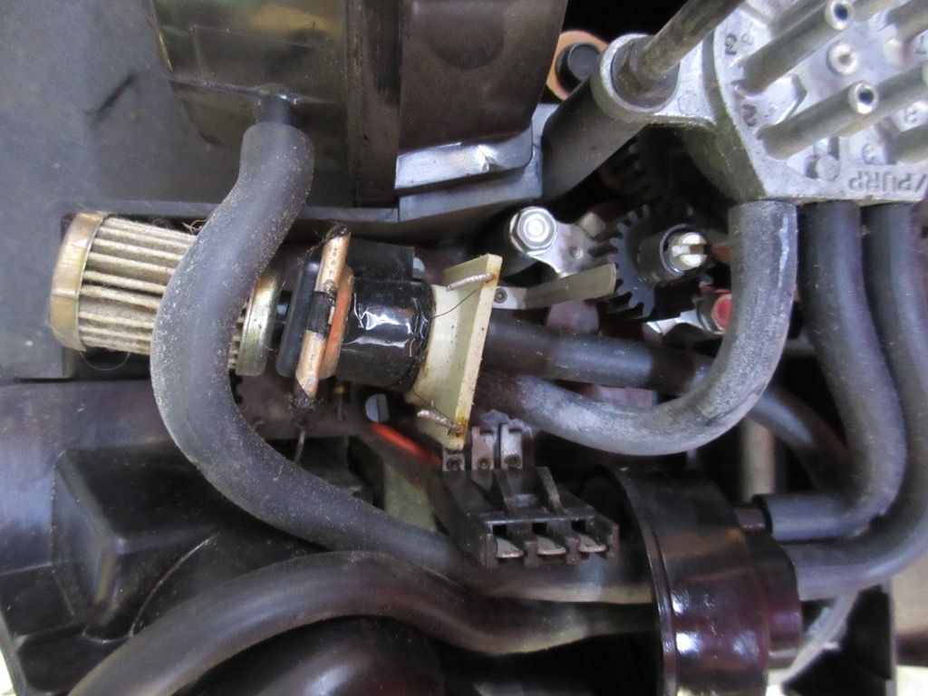
The solenoid-looking device with the air filter on the end of it is a pressure regulator. This controls the amount of vacuum applied to the diaphragm which controls the vacuum and blower speed switches, and also the output shaft which drives the blend flap. The solenoid is fed a signal from the circuit board based on the incoming sensor string and also the position of the variable resistor driven by the cog on the right. There is a slot in this which allows fine tuning of the programmer output shaft in relation to the sensor string. There is a piece of Cadillac test equipment for this but I don't have it or instructions.
There is also a test point which is a single metal terminal sticking up from the board. This gives a voltage in relation to the sensor string and should be in the range of 0 to about 1.6V for normal operation, with 12V for open circuit. Remember that an open circuit is created when the temperature control on the binnacle is set to full-hot. With the temperature control set full anti-clockwise, you should never get more than 1.6V here, so if you have 12V, you have a fault in the sensor string somewhere. This is a handy test point for setting up the system and so I have connected a wire to this test point which follows the vacuum tubes to the Control Head where it can easily be connected to.
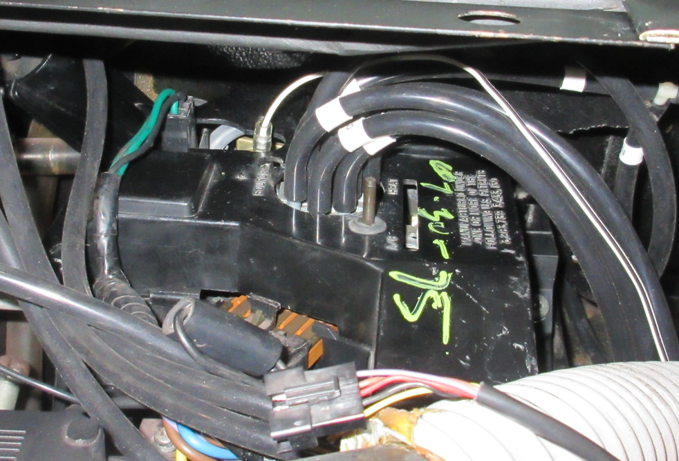
It is the single white/black wire here. |
|
| Back to top |
|
 |
jonc
Joined: 21 Sep 2010
Posts: 584
Location: Cheshire, UK
|
 Posted: Wed Jan 06, 2016 11:48 am Post subject: Posted: Wed Jan 06, 2016 11:48 am Post subject: |
 |
|
Now back to the vacuum.
This chart shows better than the AML document how the system is supposed to operate. Ignore the 'Defroster door' column.
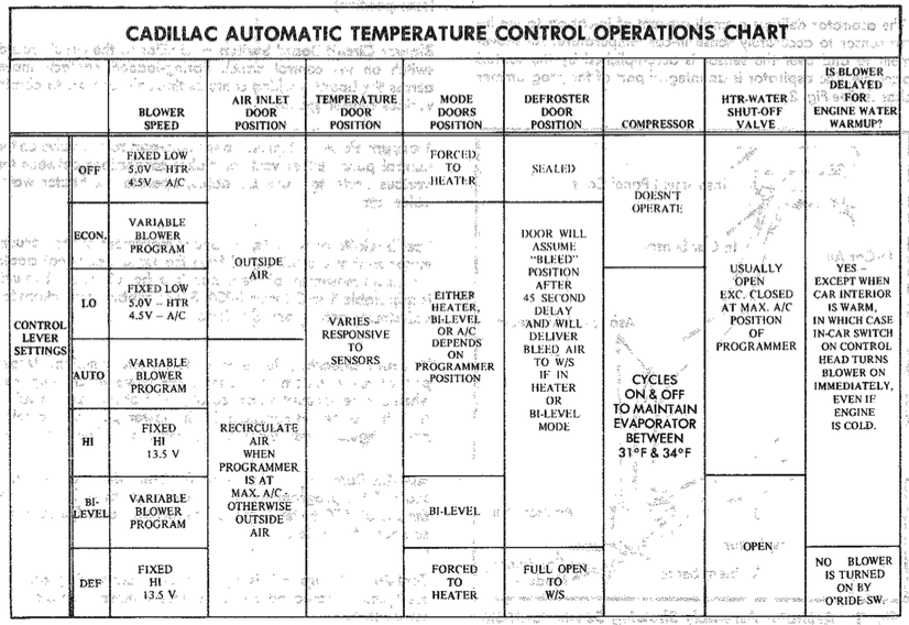
Here are the three vacuum diagrams for the Cadillacs:
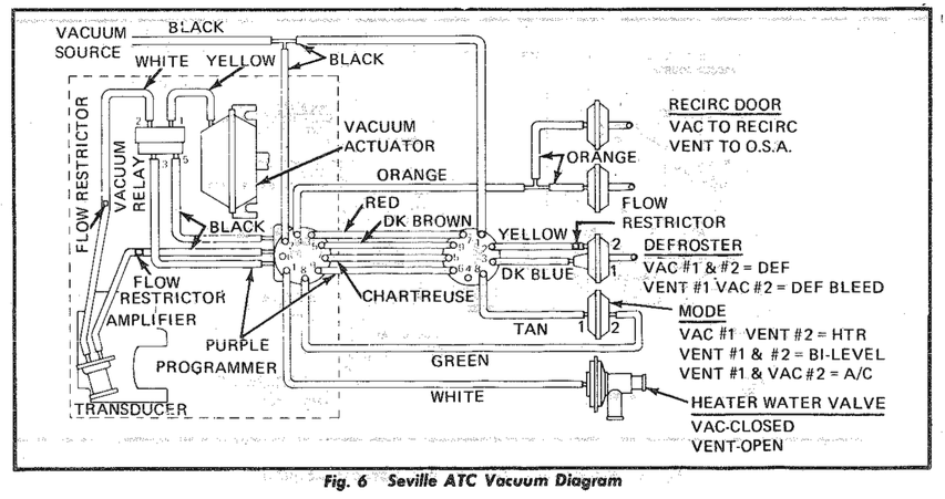
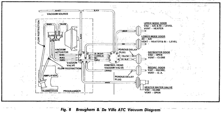
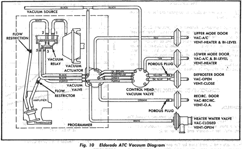
So three different ways of connecting the system. Firstly, we don't use the defroster door output as this is controlled via the microswitch and a solenoid so we can ignore/blank those ports. The heater valve is as expected too and always connected to port 1 on the Programmer.
I am also going to ignore the first diagram because it has a 'mode' diaphragm with a port on each side. I don't know what this is, and we don't have one. That leaves us with the Brougham/De Ville and Eldorado systems.
There is one difference between the two - the operation of the upper/lower vents.
Brougham/De Ville:
Upper - AC/Bi-level= vac
Lower - Heat = vent
Eldorado:
Upper - AC = vac
Lower - Bi-level /Heat = vent
Now, vacuum applied = vent closed on our system. Basically the difference is how Bi-Level mode applies - For the Brougham/De Ville, in Bi-Level mode the upper vents are closed. Not what you would expect for Bi-Level. Based on this, I would say our system should be the Eldorado piping. |
|
| Back to top |
|
 |
jonc
Joined: 21 Sep 2010
Posts: 584
Location: Cheshire, UK
|
 Posted: Thu Jan 07, 2016 7:01 pm Post subject: Posted: Thu Jan 07, 2016 7:01 pm Post subject: |
 |
|
Only one problem here - I think Lagondas use vacuum for outside air / vent for recirculate which is the opposite way round to the Cadillacs.
Maybe that's why it is different.. |
|
| Back to top |
|
 |
jonc
Joined: 21 Sep 2010
Posts: 584
Location: Cheshire, UK
|
 Posted: Thu Jan 14, 2016 10:57 am Post subject: Posted: Thu Jan 14, 2016 10:57 am Post subject: |
 |
|
Actually, that's not the case. Also, looking back at the AML vacuum diagrams, the fresh air/ recirc. actuators are connected to the face level vents anyway. This means if you get the face level vents correct, the others will be too.
Based on this, here are my suggestions using the Eldorado piping, with unused ports blanked off. There only needs to be two versions - blue button or no blue button.
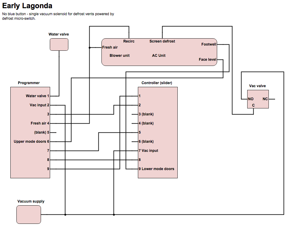
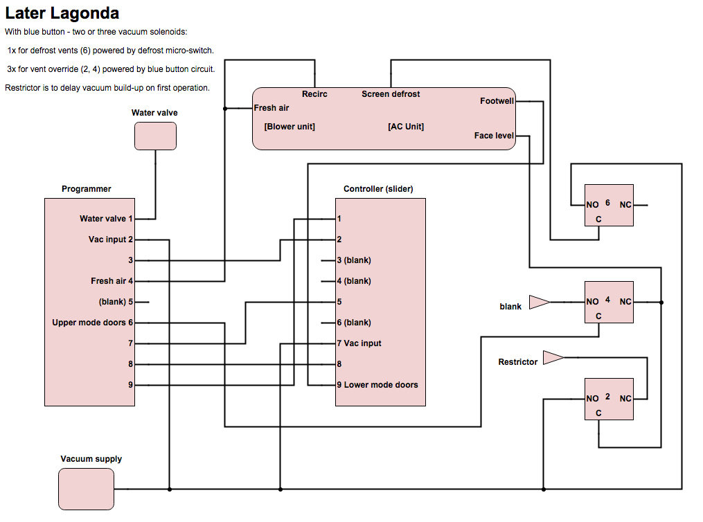
The solenoid 6 on the earlier cars is a round type which has two ports, and is another square (3 port) type on later ones. If its a round one, just connect the two pipes to what's there! Same applies to the early cars which may have a single 2 port solenoid.
Later cars I think have a single actuator for fresh air / recirculate.
I think that now concludes this thread.  |
|
| Back to top |
|
 |
Hawke
Joined: 02 Jul 2011
Posts: 29
Location: Oconomowoc, Wisconsin, USA
|
 Posted: Tue Jun 27, 2023 8:24 pm Post subject: Posted: Tue Jun 27, 2023 8:24 pm Post subject: |
 |
|
This is an old thread, but it has been very helpful (thanks, jonc!) in my efforts to diagnose the inoperative AC/ventilation system in 13557.
I'm hoping that someone may be able to tell me how to remove the AC controller (slider) from the right-side instrument binnacle of my series 4 Lagonda. All of the screws and the lower fascia panels have been removed, and the controller is loose on one (right) side. Despite my best efforts (trying not to break anything), I cannot free the left side of the controller. I need to remove and access the back of the controller to determine if I've got a vacuum leak or some other complication. Does the binnacle need to be disassembled? How is the controller secured inside the binnacle??
Thanks in advance for any help or suggestions!
_________________
Living on the [w]edge... |
|
| Back to top |
|
 |
Lagondanet
Administrator

Joined: 03 Jan 2007
Posts: 3110
Location: UK
|
 Posted: Sat Jul 01, 2023 6:56 am Post subject: Posted: Sat Jul 01, 2023 6:56 am Post subject: |
 |
|
| I will try to find out for you. |
|
| Back to top |
|
 |
|
|
You cannot post new topics in this forum
You cannot reply to topics in this forum
You cannot edit your posts in this forum
You cannot delete your posts in this forum
You cannot vote in polls in this forum
|
|


