 |
LagondaNet
|
| View previous topic :: View next topic |
| Author |
Message |
jonc
Joined: 21 Sep 2010
Posts: 584
Location: Cheshire, UK
|
 Posted: Mon May 23, 2011 8:33 pm Post subject: Posted: Mon May 23, 2011 8:33 pm Post subject: |
 |
|
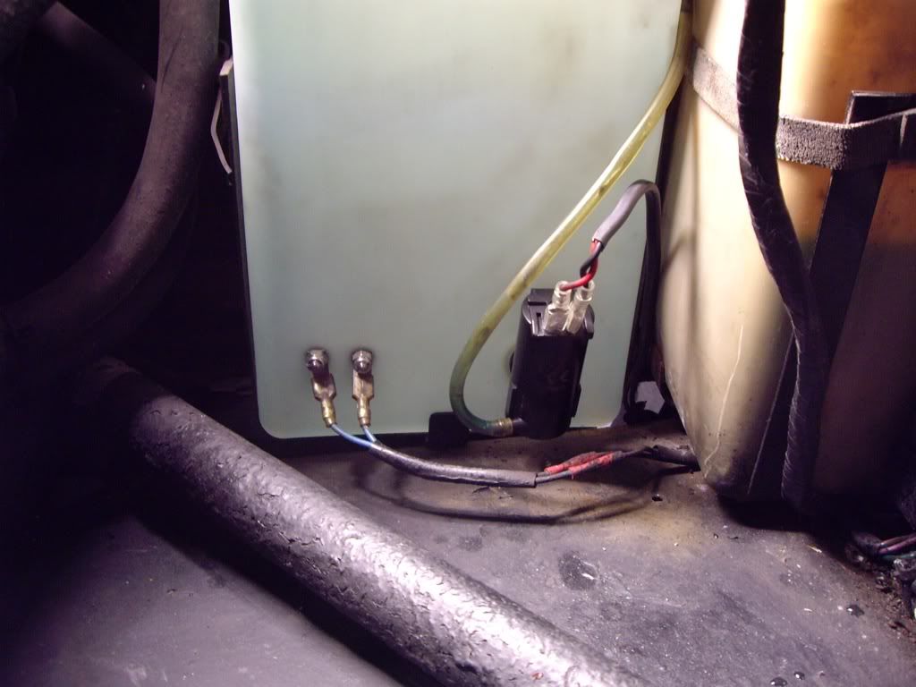
Now to the other side. I have two washer pumps - the original one, broken and with the water outlet sealed up, and another one bolted down with a pipe feeding in through a hole in the cap on the top of the bottle. Also broken, and connected with some nasty blue crimps.
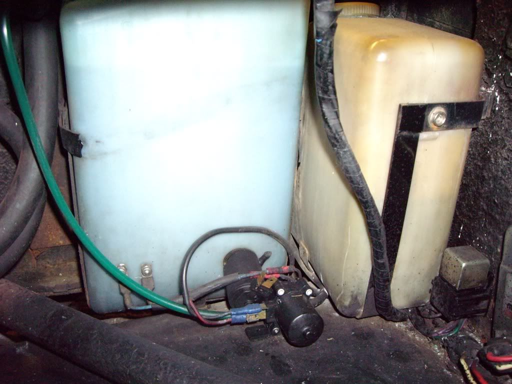
The original one fits through a 20mm hole in the side of the bottle. Halfords sell a generic replacement so I have no idea why a separate one was fitted. Here's the finished job. No time to sort the wires for the level sensor right now - added to the list..
 |
|
| Back to top |
|
 |
jonc
Joined: 21 Sep 2010
Posts: 584
Location: Cheshire, UK
|
| Posted: Tue May 24, 2011 9:34 am Post subject: |
|
|
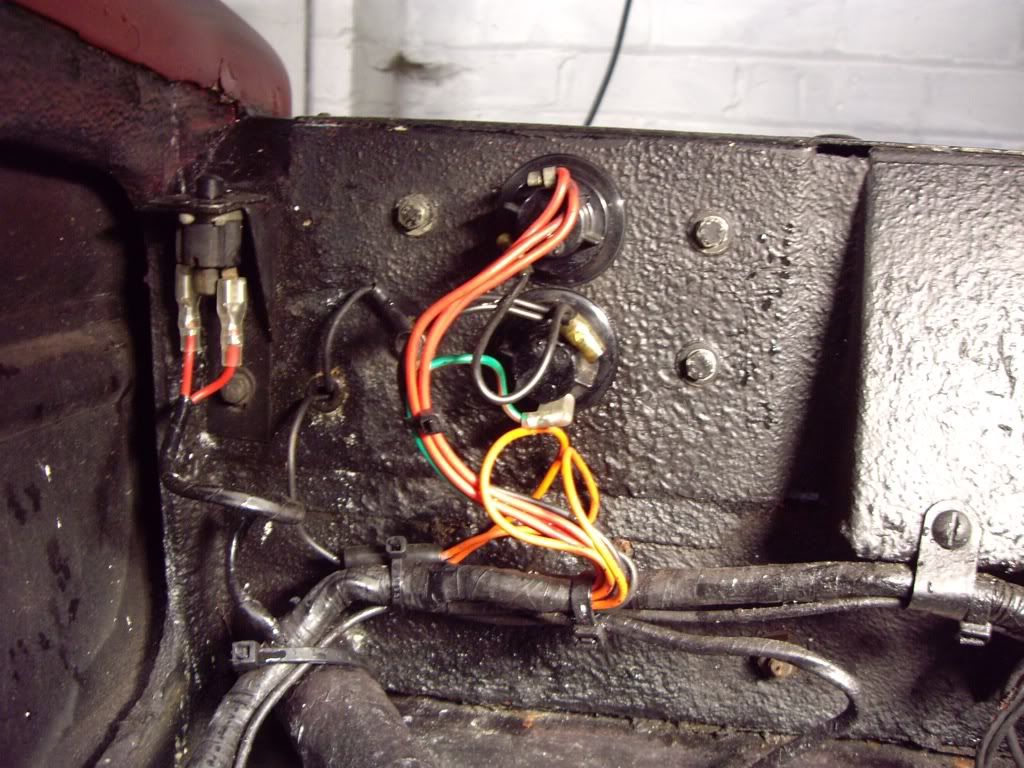
Final job at the front for now. While I was in this area, I thought I would do a bit more loom tidying. There are some more blue crimps here, and its generally a bit messy:
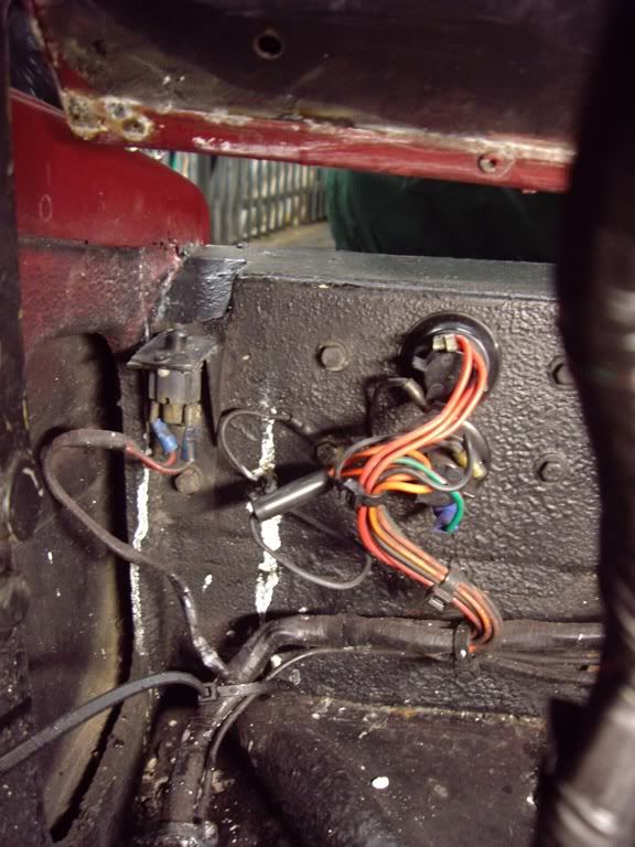
I replaced the crimps with the correct ones, and also removed and cleaned the lamp holders to make sure the bulbs had a good contact. I did this in the ultrasound bath. I found that the wrong side light bulbs had been fitted at this point - they were 21W (the same as the indicators) when they should be 5W. An additional 32W equals around 3A additional current through the wiring and side light relay - probably not a good idea.
Correct bulbs fitted, existing connectors cleaned and greased and it went back together like this:
 |
|
| Back to top |
|
|
jonc
Joined: 21 Sep 2010
Posts: 584
Location: Cheshire, UK
|
| Posted: Tue May 24, 2011 7:44 pm Post subject: |
|
|
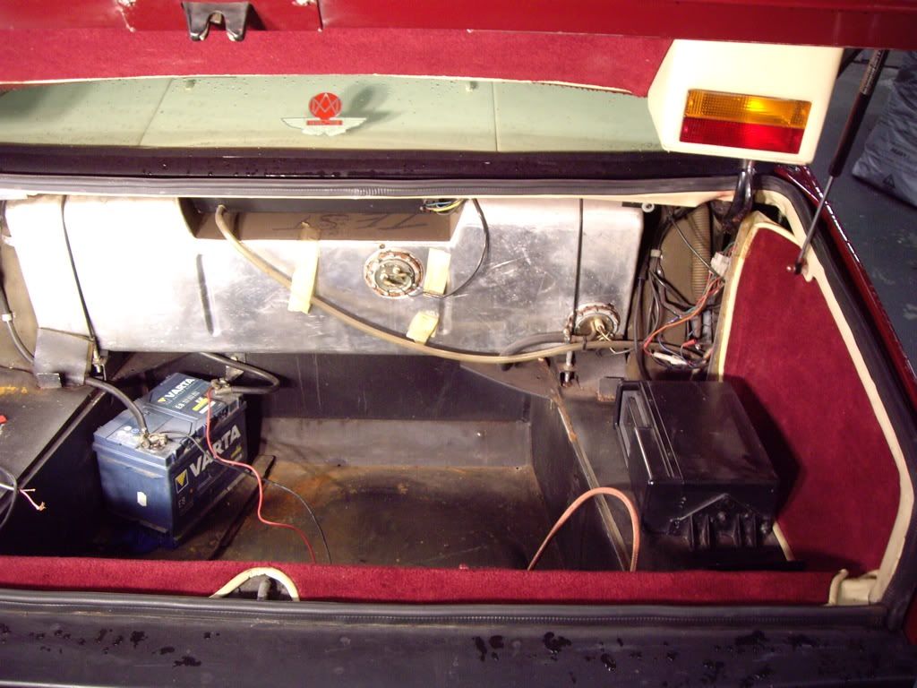
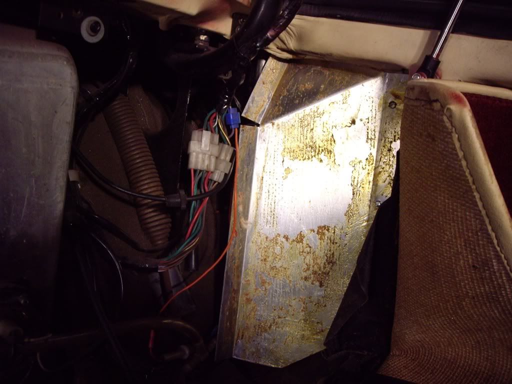
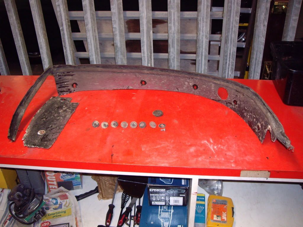
A bit of tidying in the boot now. The back panel was loose and lifted straight out. Also, the panel on the right had been bent out to fill a gap:
I thought that the tatty bit of flimsy ply wood was a later replacement - not so:
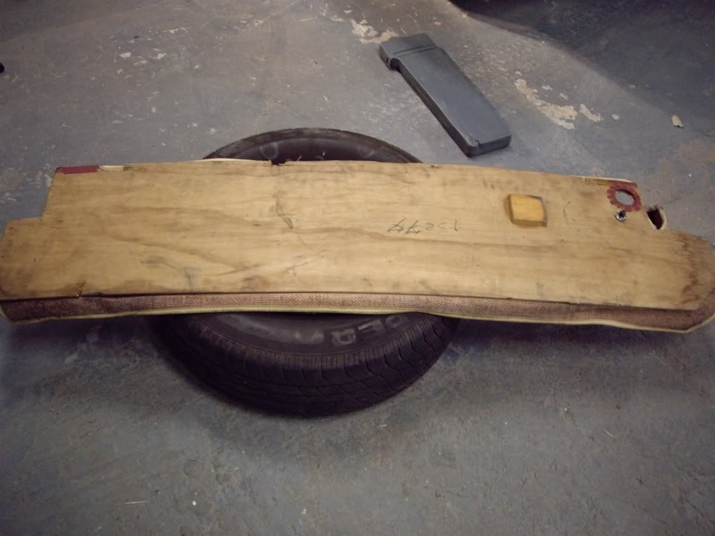
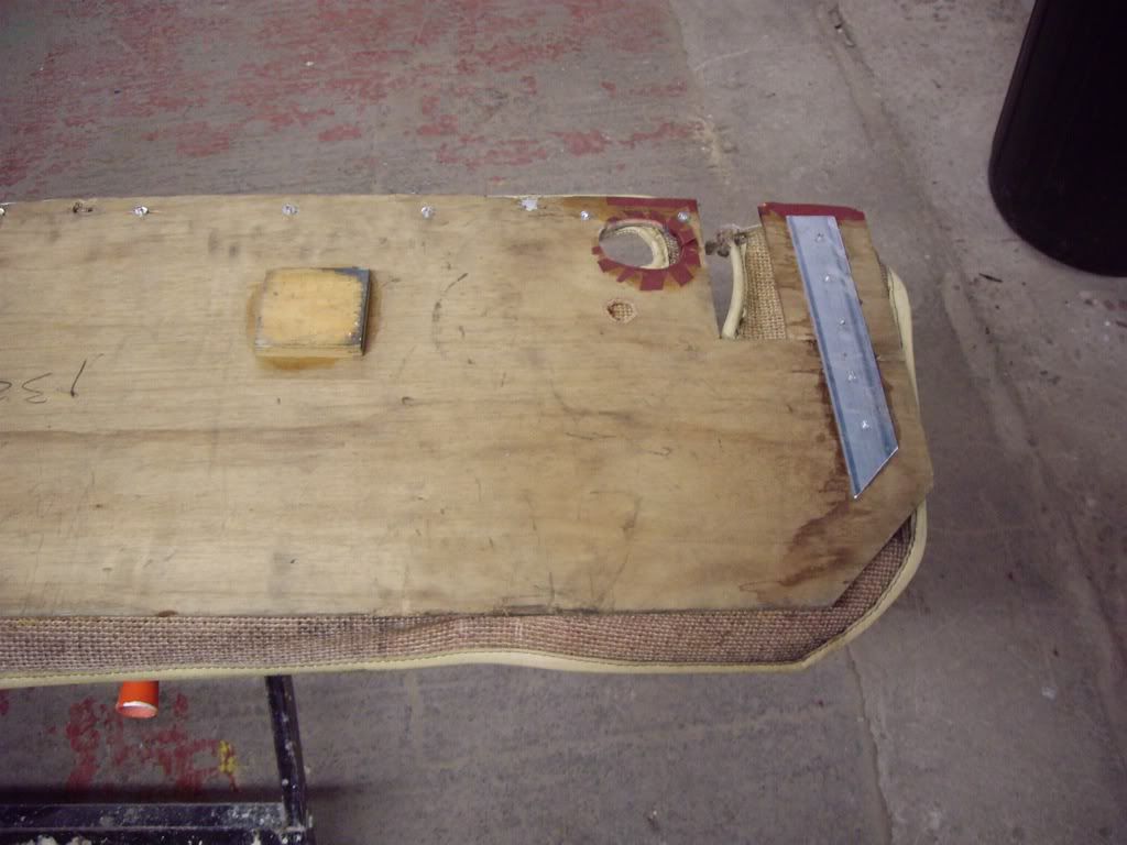
The top edge was damaged at each of the four points it fixes and so I glued and riveted an aluminium strip along the top edge, and another on each side to support the area at the side of the slot for the boot hinge.
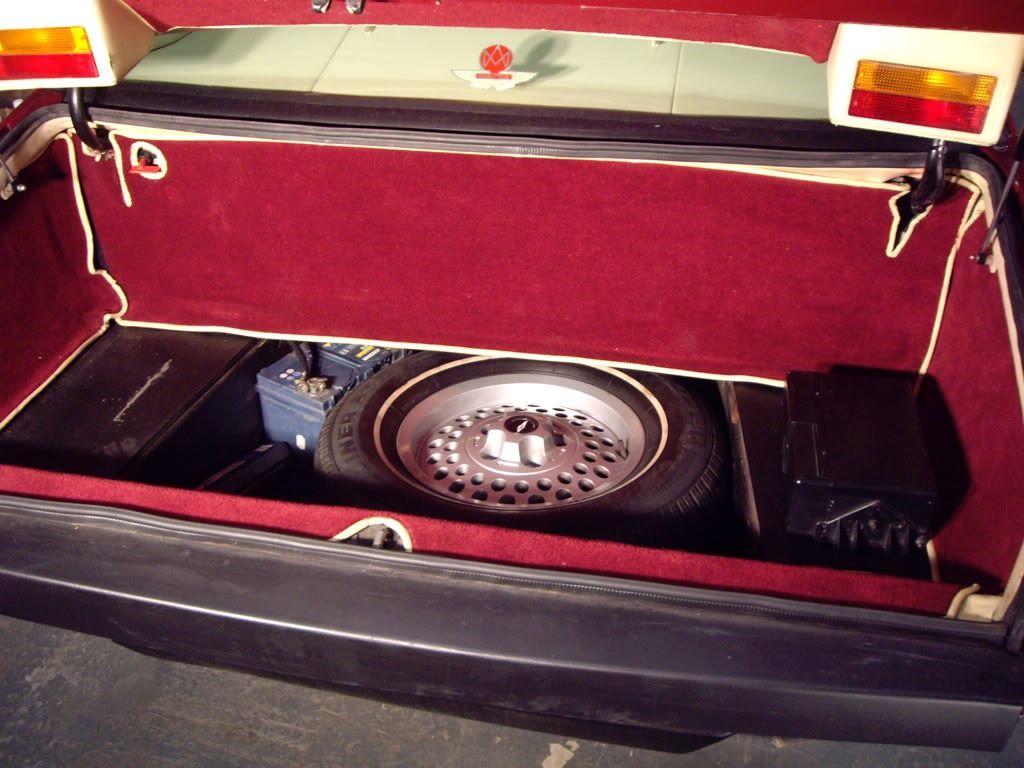
Odd that there is no evidence of holes to fix the bracket for the tool kit - I had always assumed the bracket was removed when the new boot carpet was fitted. Maybe it was never there?
The aluminium plate on the right side is there to finish the trim around the electric aerial. Here it is back in proper shape:
And the panel back in place. I had to drill four holes in the aluminium strip along the top and secured it in place with four M4 screws:
Last edited by jonc on Sat May 28, 2011 12:42 pm; edited 1 time in total |
|
| Back to top |
|
|
jonc
Joined: 21 Sep 2010
Posts: 584
Location: Cheshire, UK
|
| Posted: Sat May 28, 2011 11:46 am Post subject: |
|
|
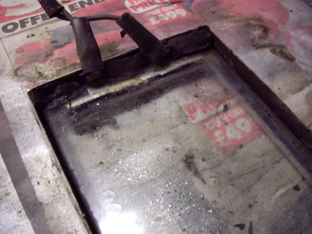
Now I was getting close to the AMOC Spring Concours, so time for an essential cosmetic job. The lamp glasses were dirty on the inside, which really lets the car down:
I have been a bit worried about how delicate the lamp glasses were, whether they would come off in one piece, and what I would find behind. In the end it wasn't too bad - they are held in place by three small self-tapping screws at the top, and two at the bottom inside which are accessed by removing the two rubber bungs on each side. All the screws are stainless steel, as is the glass surround and so they all undid easily. The lamp glass is heated by filaments built into the laminateg glass like the heated rear window and the two wires go through the panel to the loom next to the indicator and sidelight wires. These have to be disconnected before removing the glass. Where they connect on to the glass, they are quite delicate - the wires are soldered onto the foil which comes out of the side of the glass:
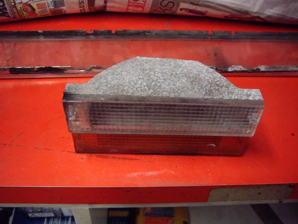
One wire disconnects from a bullet connector and the other is an earth tag which then push through a grommet. The earth tag it tight and it is easier to remove the grommet before feeding the wires through. Here is the result:
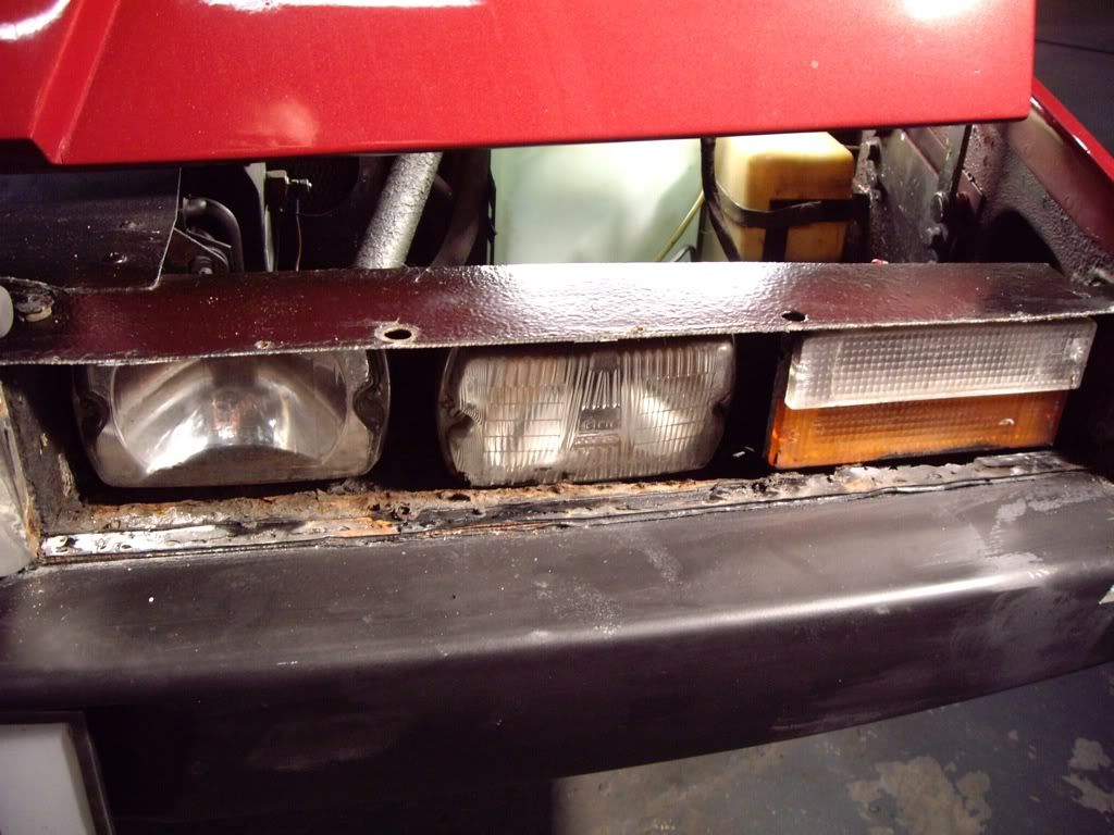
The inside is pretty tatty - this wasn't really visible when the glass was dirty, but when it is clean it will look a mess. I decide to clean away the crud, surface rust etc. and give it a quick repaint. |
|
| Back to top |
|
|
jonc
Joined: 21 Sep 2010
Posts: 584
Location: Cheshire, UK
|
| Posted: Sat May 28, 2011 11:51 am Post subject: |
|
|
I take out the light units. I don't have time to remove the shells from the fog/spots so I just take the fronts off to give better access to clean / repaint the bottom of the recess. The back looks ok - it's the bottom where the water has collected which needs a clean up.
Here are the light units:
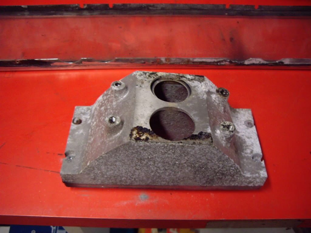
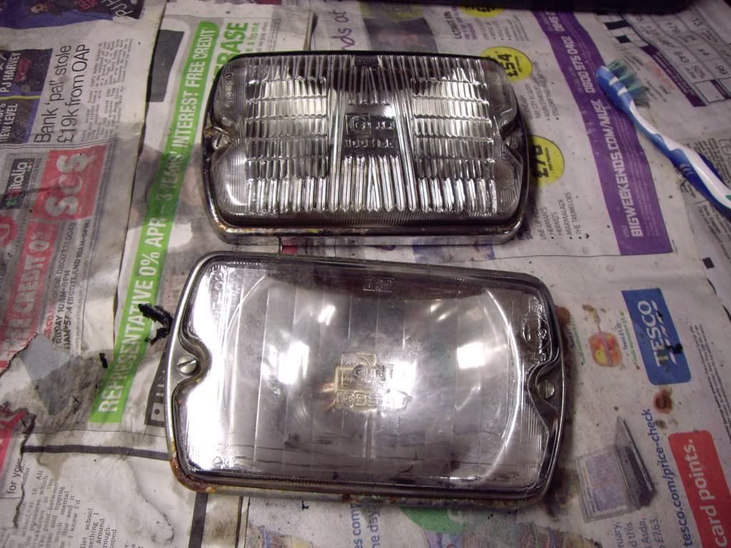
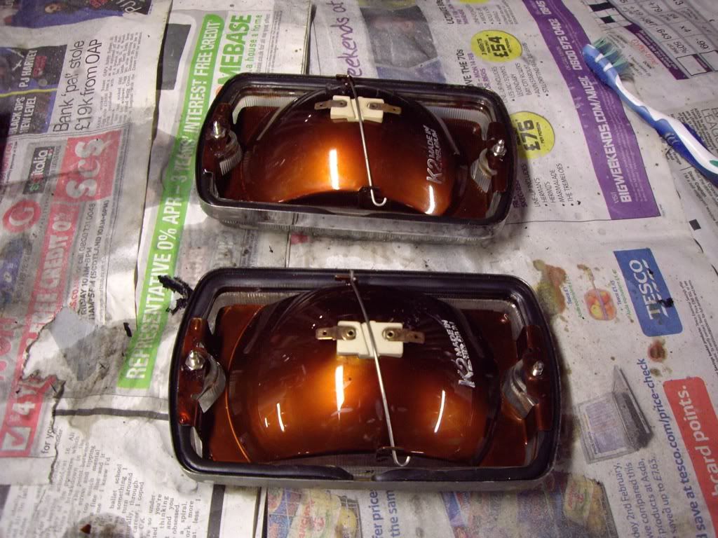
They all get a clean and polish ready for reassembly. |
|
| Back to top |
|
|
jonc
Joined: 21 Sep 2010
Posts: 584
Location: Cheshire, UK
|
| Posted: Sat May 28, 2011 12:02 pm Post subject: |
|
|
Once repainted, it all goes back together. The glass was sealed in place with silicone sealant. There appears to be no designed-in seal to stop water getting in around the edges of the stainless steel trim and so this looks like the only solution. Instead of bedding-in the trim with sealant which made it more difficult to remove, I put a bead of clear silicone around it once it is back in place. I have a feeling they will be coming out again soon anyway and this will make it easier.
The other side received the same treatment. Here you can see the black silicone along the bottom which in the photo makes the bottom steel piece above the bumper look bent - it's not - that's the silicone.
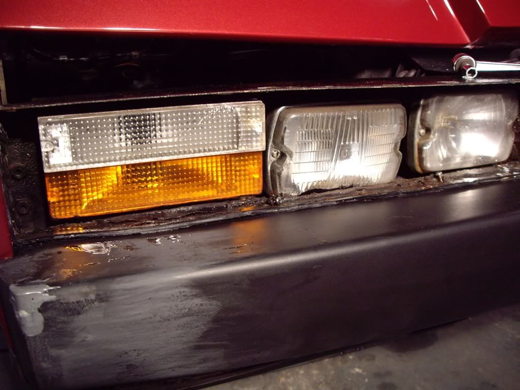
You can also see on this photo that I am filling in a small nick in the corner of the bumper. I used 3M EZ Sand Flexible Parts Repair, which I had to get from the US.
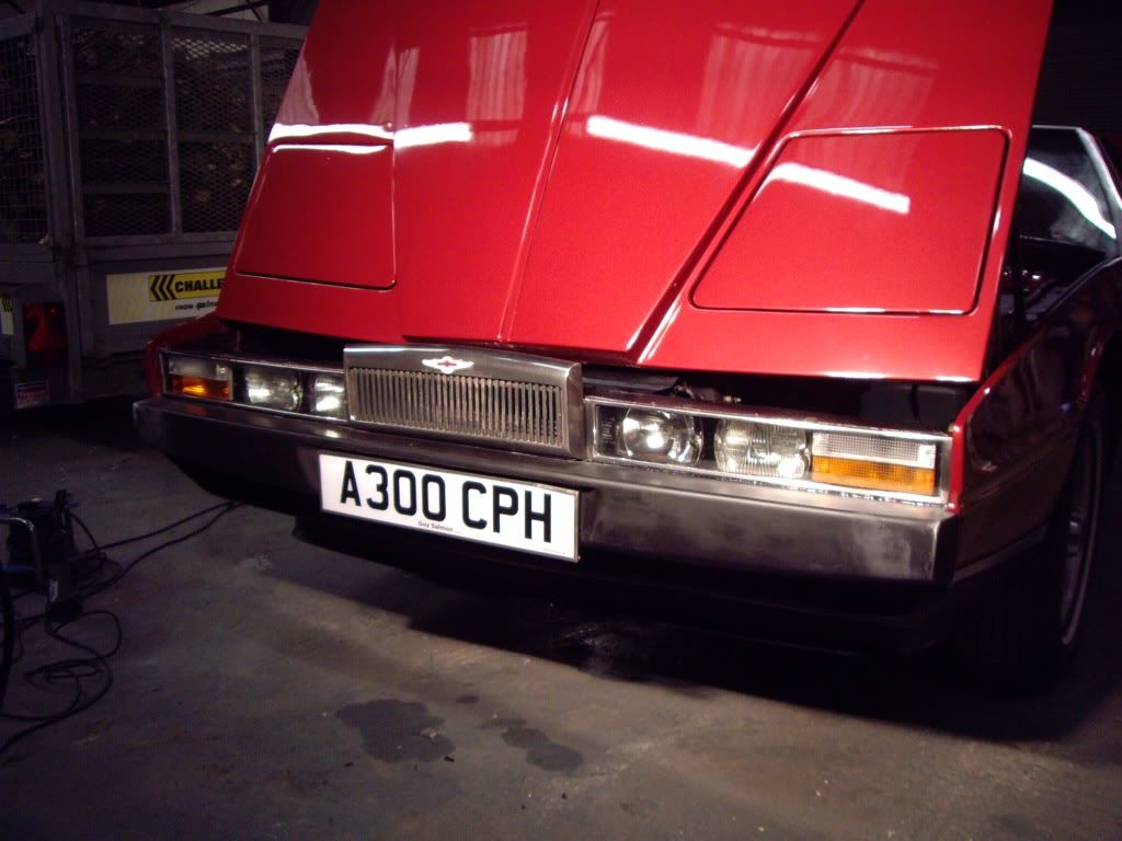
Here is the finished result with the lights back together (and before the bumper was painted):
 |
|
| Back to top |
|
|
jonc
Joined: 21 Sep 2010
Posts: 584
Location: Cheshire, UK
|
| Posted: Sat May 28, 2011 12:36 pm Post subject: |
|
|
Last job before AMOC Concours - the brakes have always been rubbish on the car, even though it has recently had a new servo and front disks. I have been thinking about this for a while, and I had figured it was probably a vacuum problem.
Vacuum is fed to the brake servo from a metal pipe at the back of the engine on top. This is connected to the rear inlet manifold on both sides via two non-return valves. I figured the problem was most likely the valves.
I removed one of the valves to see if it worked - you should be able to suck air through it in one direction only. I could see through it, so no chance of it operating as a valve. The other one was the same. This meant that the brakes had servo operation only when the engine was creating a vacuum - so when you took your foot off the accelerator and immediately braked it was there. However, there was not enough vacuum, and not for long enough to help with an emergency stop!
With a 270 mile round trip I figured it was best to replace the valves. They looked like pretty generic items, and so should be easy to locate and cheap. Here they are:
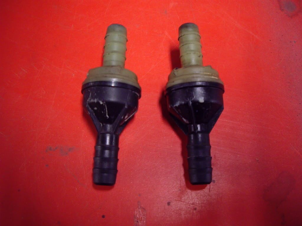
I don't have much time to research this, so I figured Jaguar would be a good place to start. It turns out the Jaguar part number is CAC4188 and they are used on the XJS amongs other cars. Most annoyingly, you seem to be able to get them in the USA for $8, whereas a Jaguar supplier in the UK charges £32 each plus VAT. I managed to get two from SNG Barrat in time for the trip. Brakes are now pretty good. |
|
| Back to top |
|
|
jonc
Joined: 21 Sep 2010
Posts: 584
Location: Cheshire, UK
|
| Posted: Sat May 28, 2011 12:40 pm Post subject: |
|
|
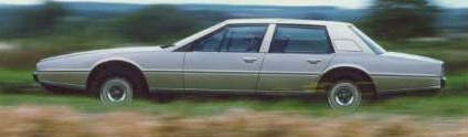
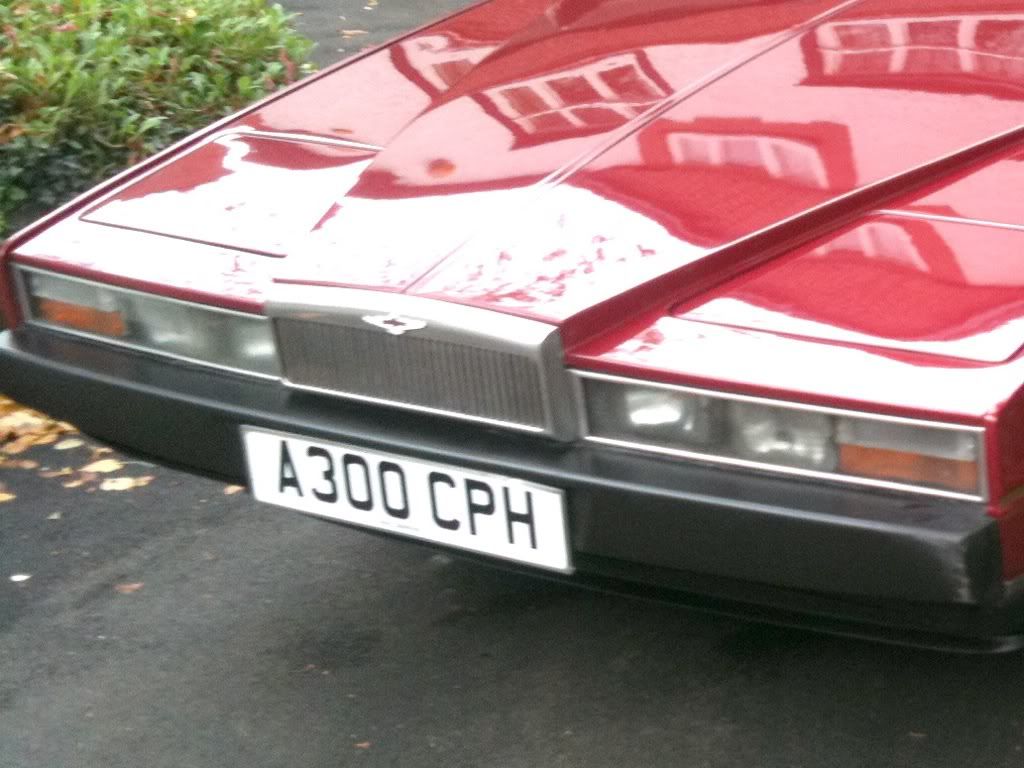
And with a bit of spit and polish, the car was ready for the concours. Here it is on display:

The 270 mile round trip was uneventful and the car behaved well. You can just see Roger's car on the left - of course he won the class - I was just happy to be there  |
|
| Back to top |
|
|
Lagondanet
Administrator

Joined: 03 Jan 2007
Posts: 3108
Location: UK
|
| Posted: Sat May 28, 2011 1:34 pm Post subject: |
|
|
| Great job Jonathan. The bottom of the lights is notorious for corrosion. Once you open them up, remove the bumper or front grill, you invariably find rust. |
|
| Back to top |
|
|
jonc
Joined: 21 Sep 2010
Posts: 584
Location: Cheshire, UK
|
| Posted: Sat Nov 26, 2011 1:41 pm Post subject: |
|
|
Since the car came back from the concours, I have been working on and off in one of the front wheel arches. I will report on that when it is finished, but I decided to have a break the other day and fix some wiring in the passenger door.
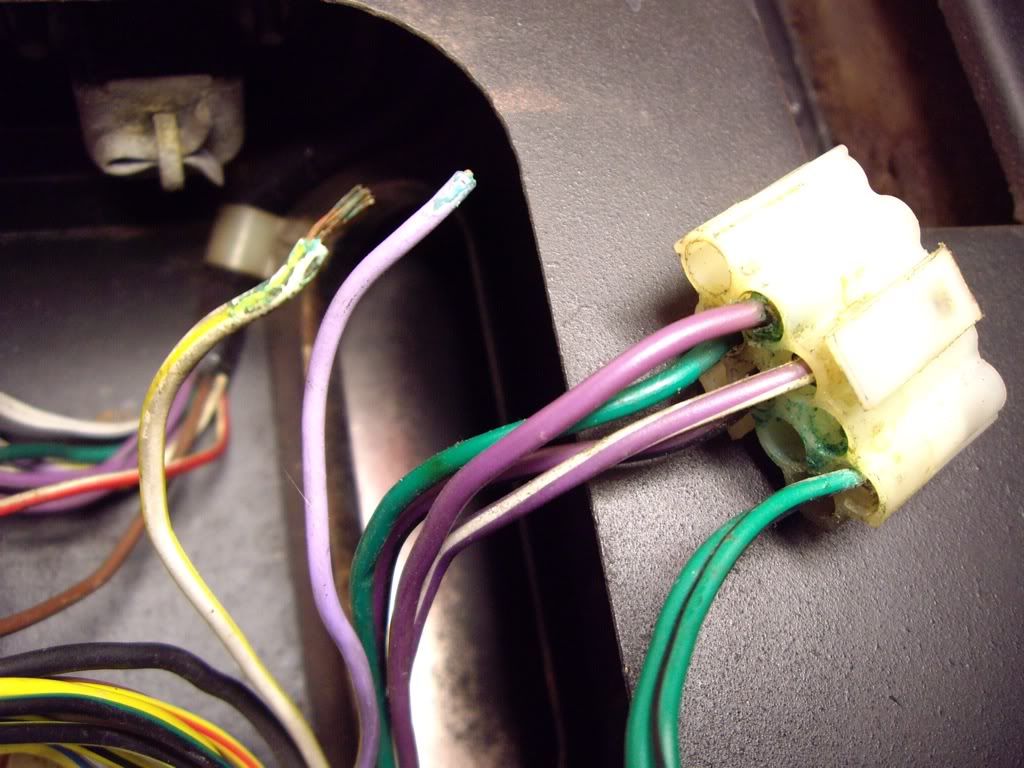
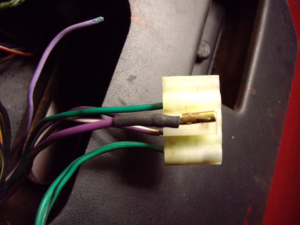
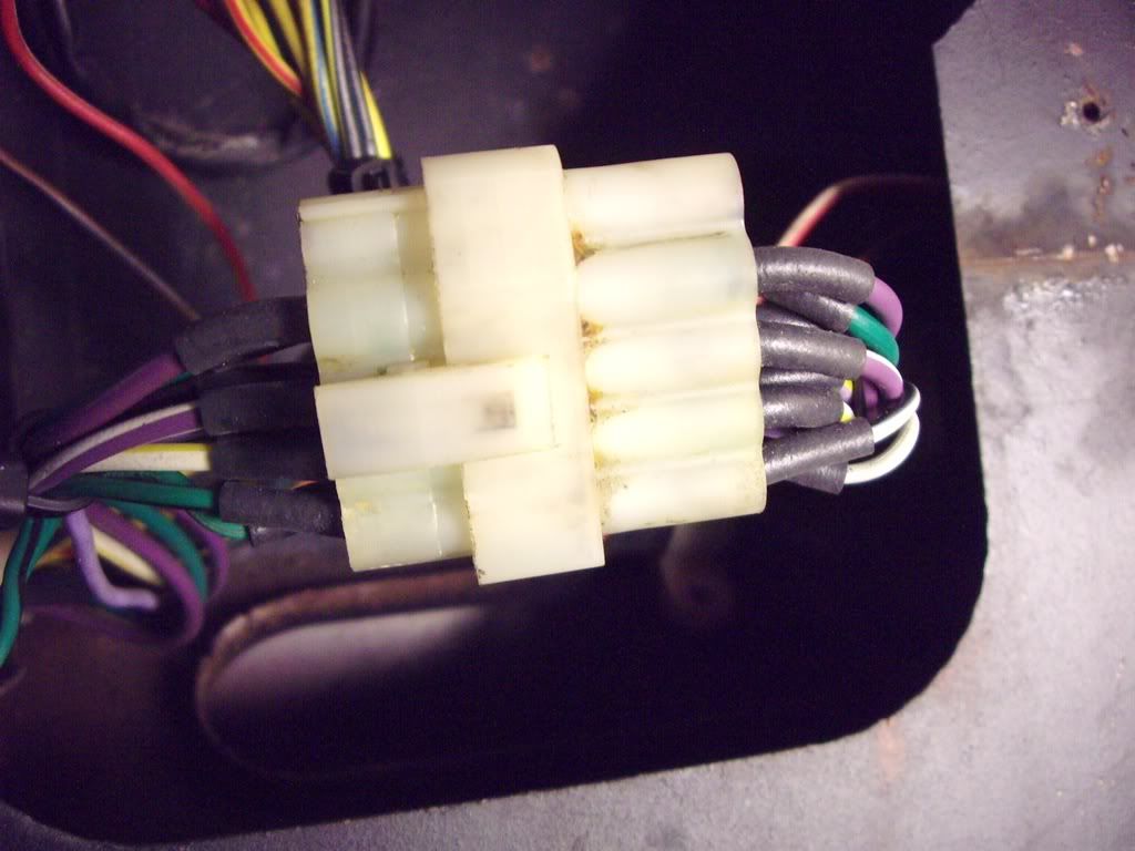
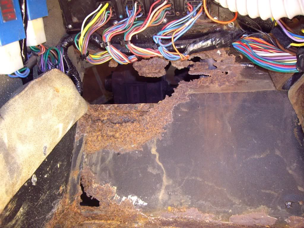
One of the connectors was positioned so that water leaking through the seal on the quarter light dripped onto it. This has caused some corrosion:
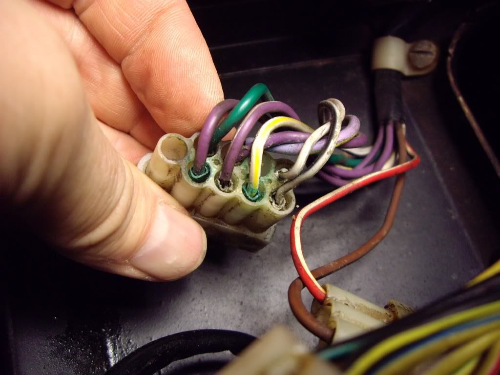
Some of the brass crimps had loosened up so the wires fell out, some were so brittle they broke apart.
To fix this, each crimp had to be removed from the connector housing, cleaned and checked, and then either put back (if ok) or replaced. I use a precision screwdriver to bend a small clip on the brass crimp which secures it in the housing and then pull out the crimp to the rear. Here is one removed:
I cleaned them with DeoxIT D5 and a small brass wire brush. Once cleaned, they look like this:
 |
|
| Back to top |
|
|
jonc
Joined: 21 Sep 2010
Posts: 584
Location: Cheshire, UK
|
| Posted: Sat Nov 26, 2011 1:51 pm Post subject: |
|
|
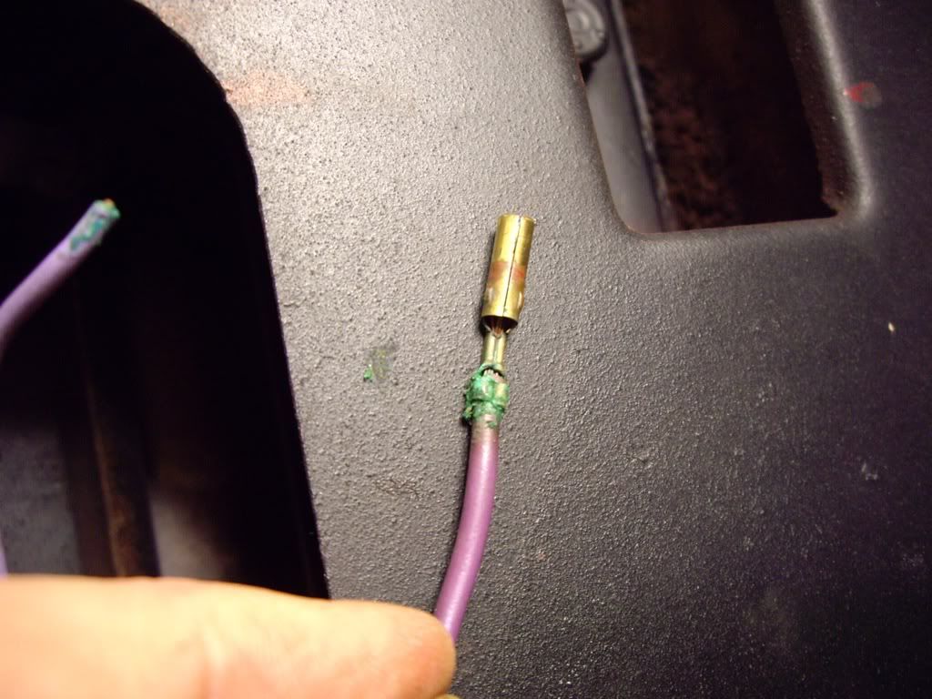
To help protect them in future, and to improve the strain relief, I am fitting a Hellerman sleeve to each crimp before refitting:
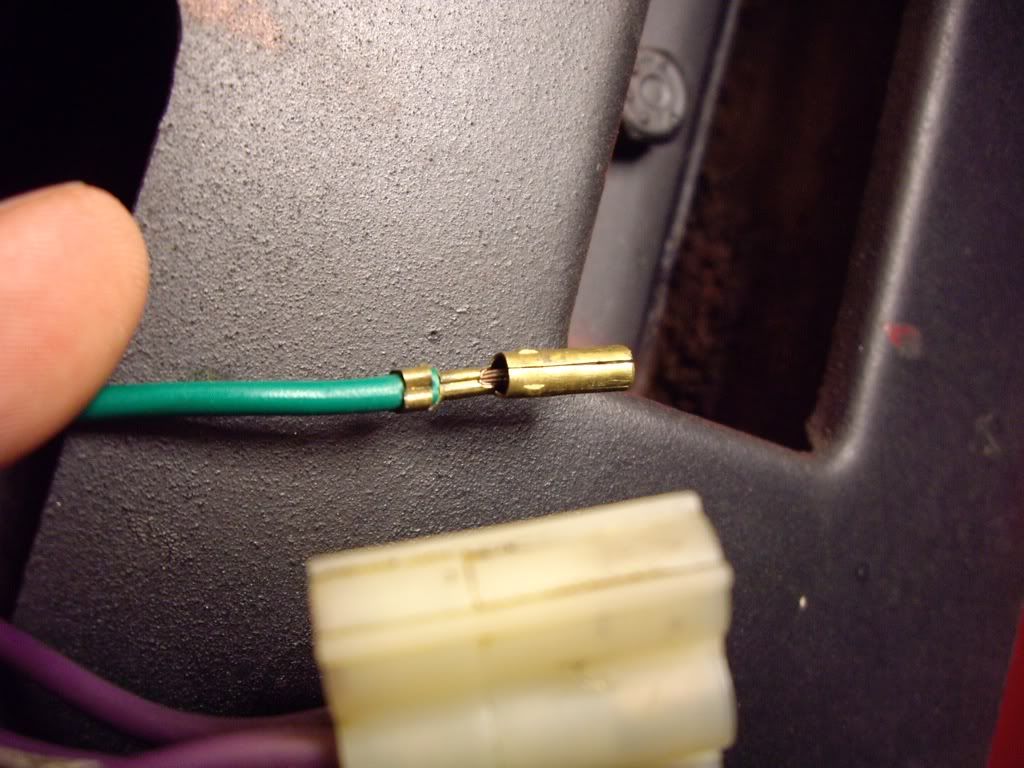
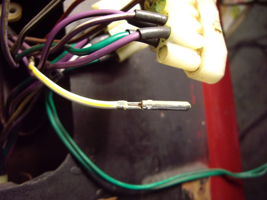
Some crimps needed replacing. I found that the connectors are available from Holden. They are their 3mm round pin connectors:
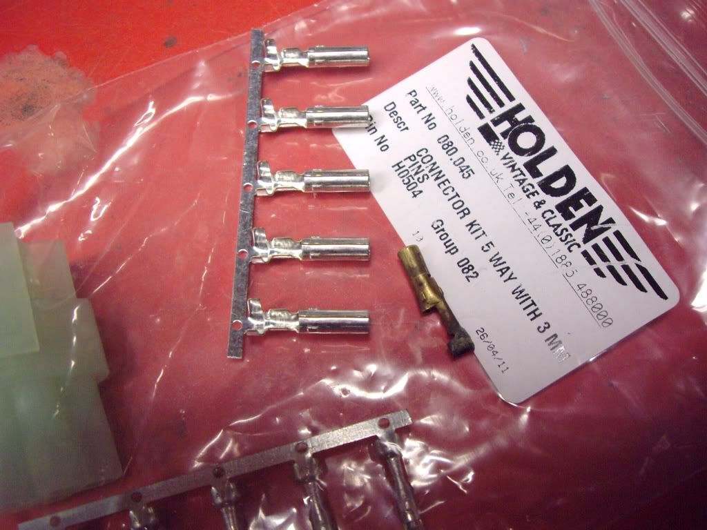
I am just using the crimps from the pack. Before I could fit a crimp, I needed to make sure the wire was free from corrosion; stripping back the insulation a bit still showed copper wire with surface corrosion, and I didn't want to shorten the wire. I found that the D5 was not strong enough to do the cleaning quickly; instead I used concentrated phosphoric acid which removed the surface corrosion in 10 or 20 seconds. I then washed the wire with the D5. Here is a new crimp fitted:
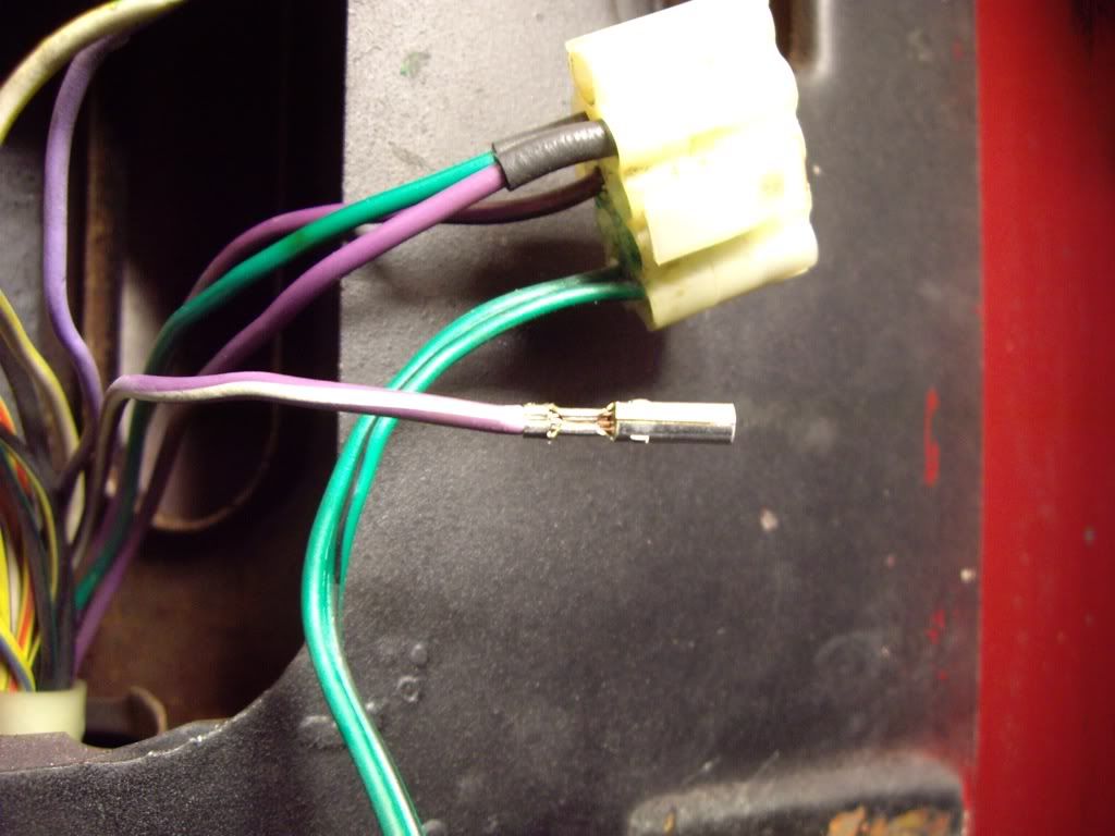
..and that side of the connector finished:
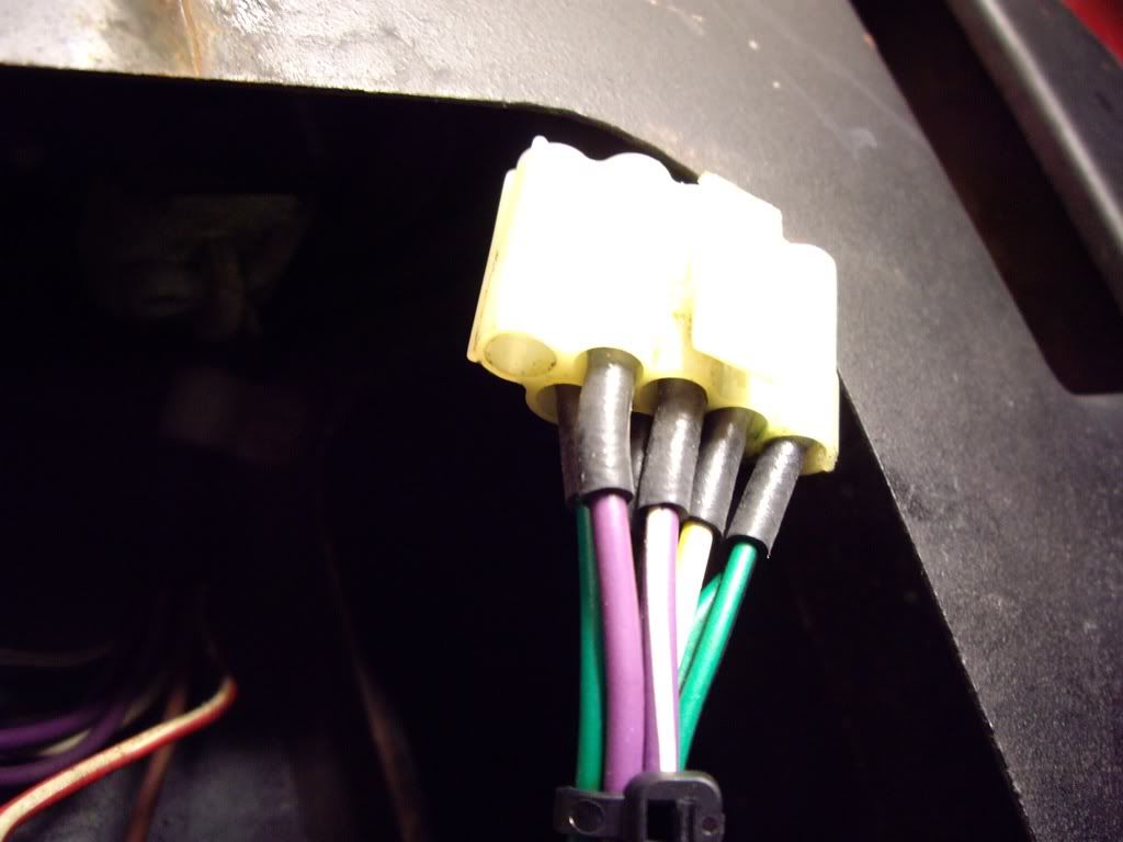
The other side, with the males was done exactly the same way:
I just had to make sure all crimps went back into the plastic body so that they 'clicked' into place. If not, when the two parts were mated up, the pins could push out. I then applied some Contralube to each female crimp before putting it back together.
Finished job. It will be positioned so that any water will not drip onto it.
 |
|
| Back to top |
|
|
Lagondanet
Administrator
Joined: 03 Jan 2007
Posts: 3108
Location: UK
|
| Posted: Sun Nov 27, 2011 10:54 am Post subject: |
|
|
Jonathan,
Meticulous & marvellous. I wish I had your patience and obvious expertise. |
|
| Back to top |
|
|
jonc
Joined: 21 Sep 2010
Posts: 584
Location: Cheshire, UK
|
| Posted: Sun Feb 26, 2012 3:21 pm Post subject: |
|
|
Ok, time for an update.
After the spring concours I thought I would give the front wheel arches a bit of a clean. There was a fair bit of mud in there, and I could see some surface rust. With the front of the car in the air, and the wheels off, I started prodding at the left arch and sill where it meets the wing since this didn't look quite straight and seemed to have some mud behind the stainless trim.
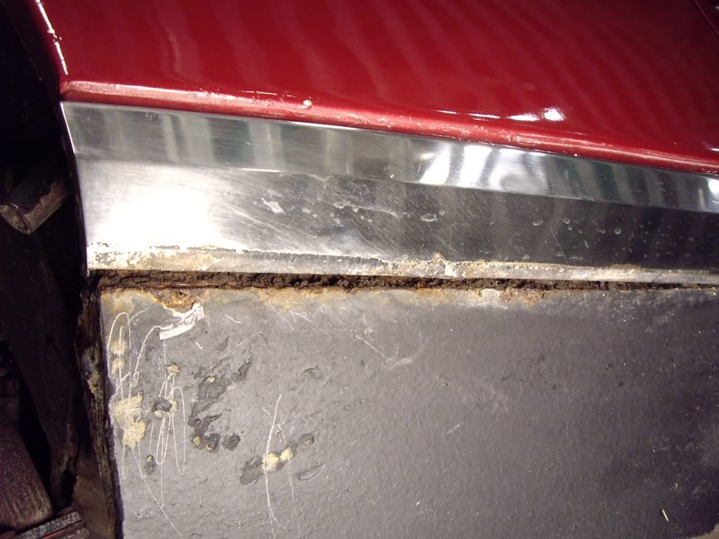
It soon became clear that the mud was holding some of this area together..
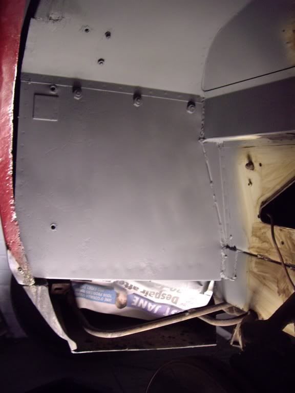
I started taking the heat shields off for a better look. These are held in place with bent metal tabs:
and from the inside:
Next I took off the aluminium plates which help fill the gap between the steelwork and the wing. They are held in place with M6 screws and big washers. On the edge is a rubber seal and the whole lot is sealed with some sort of black sealant which was very hard and brittle.
 |
|
| Back to top |
|
|
jonc
Joined: 21 Sep 2010
Posts: 584
Location: Cheshire, UK
|
| Posted: Sun Feb 26, 2012 3:39 pm Post subject: |
|
|
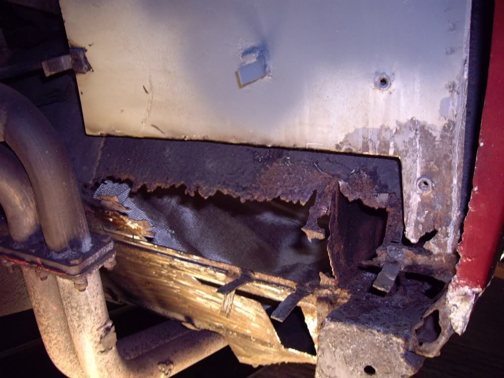
Next the stainless steel trim was removed from the wing. This was held in place with rivets on the bottom and front edge and clips on the top edge.
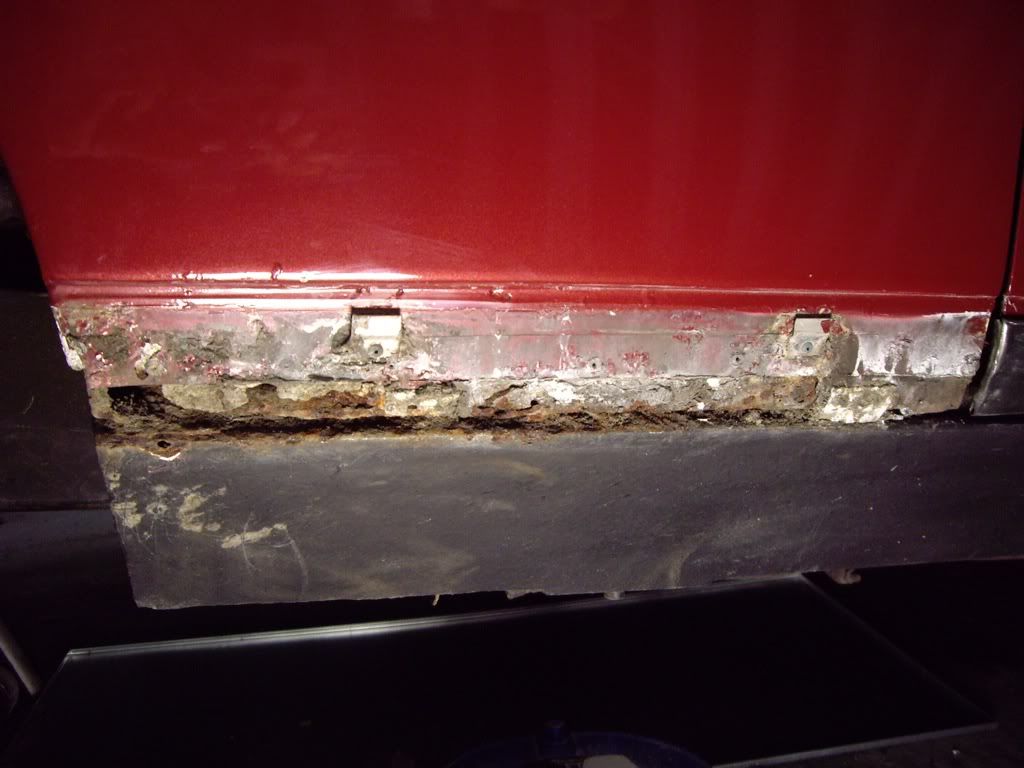
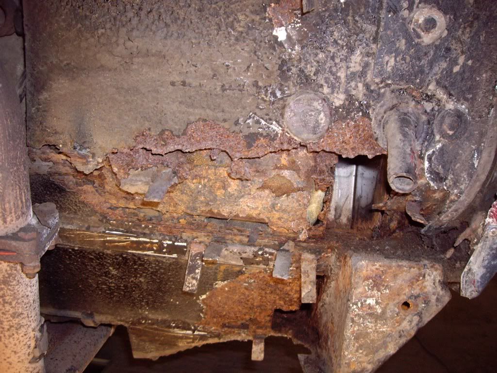
The front part of the steel which the wing is riveted to is full of holes and I can see the rot has extended to the top of the sill.
Time to see what state the sill is in so I removed the paint and a thin skim of filler:
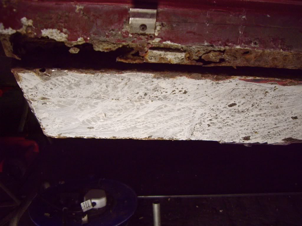
Its still pretty good. I can see there has been some work before. This is of a very good quality and I am pretty sure it was done by Four Ashes some time ago as I have an invoice in the history file.
Time to start stripping back so I can do some repairs.
I am removing all the underseal from the arch to use a more modern equivanent, and to remove all the surface rust. This takes an age - hot air paint stripper and scraper, then panel wipe on kitchen roll to remove the last of it.
Rust is removed with a combination of flap wheel on grinder and concentrated phosphoric acid, and then primed with a zinc-rich primer.
Last edited by jonc on Mon Feb 27, 2012 11:25 am; edited 1 time in total |
|
| Back to top |
|
|
jonc
Joined: 21 Sep 2010
Posts: 584
Location: Cheshire, UK
|
| Posted: Sun Feb 26, 2012 3:58 pm Post subject: |
|
|
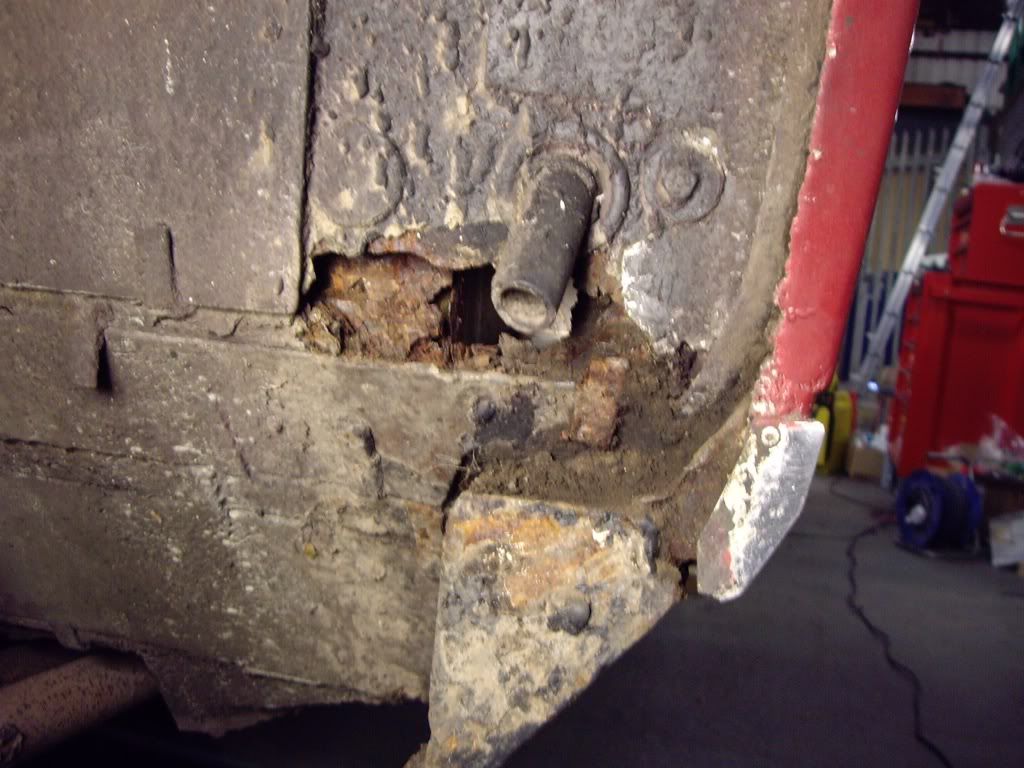
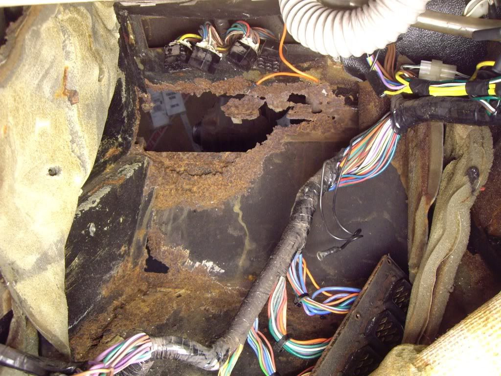
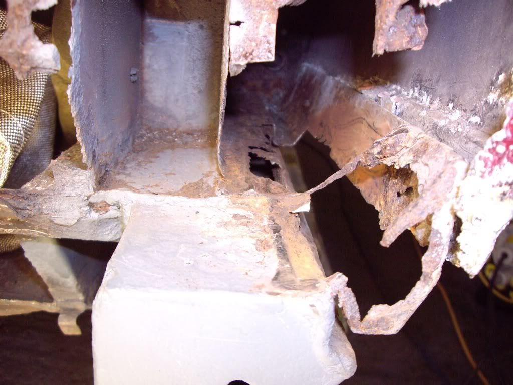
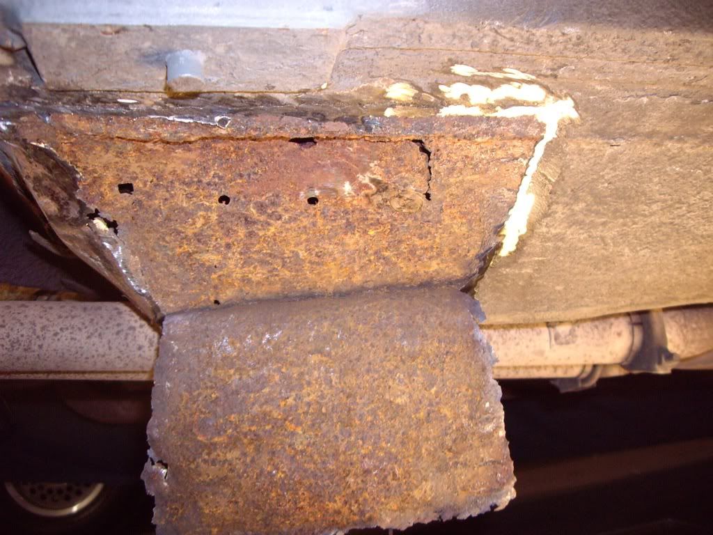
Now time to cut out the rusty metal back to good:
The construction in this area is really complex, and so it was important to work out what joined on top of what, and what the shapes were. I also had to work out what order to cut/make/weld in to put it all back correctly. Here you can see the extent of the hole in the top of the outer sill, but it also gave me the shape of the contour of the metal which supports the wing bottom edge.
I actually managed to weld in the new metal at the top of the sill without cutting off the wing bottom. This involved detaching the bottom edge and easing it out. I then used a long-nosed die grinder with a two inch cutting disk to cut out the metal and then welded in the new metal. I was obviously having such a great time that I appear to have forgotten to photograph it.
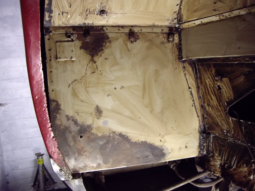
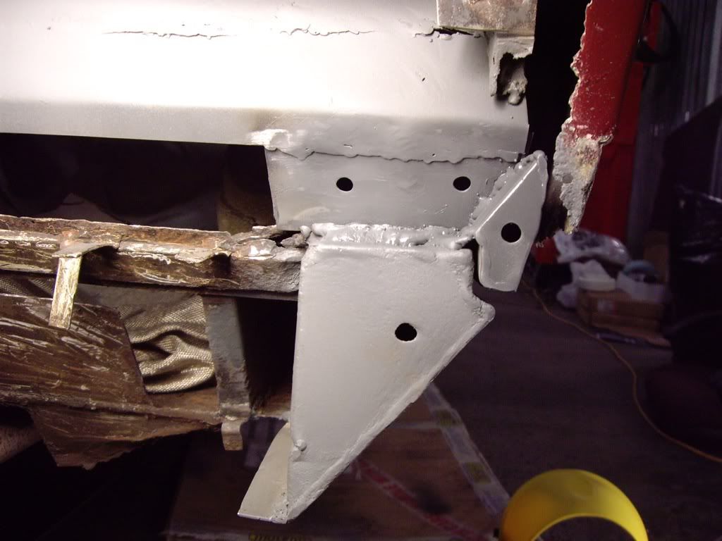
Here the metal is starting to go back in:
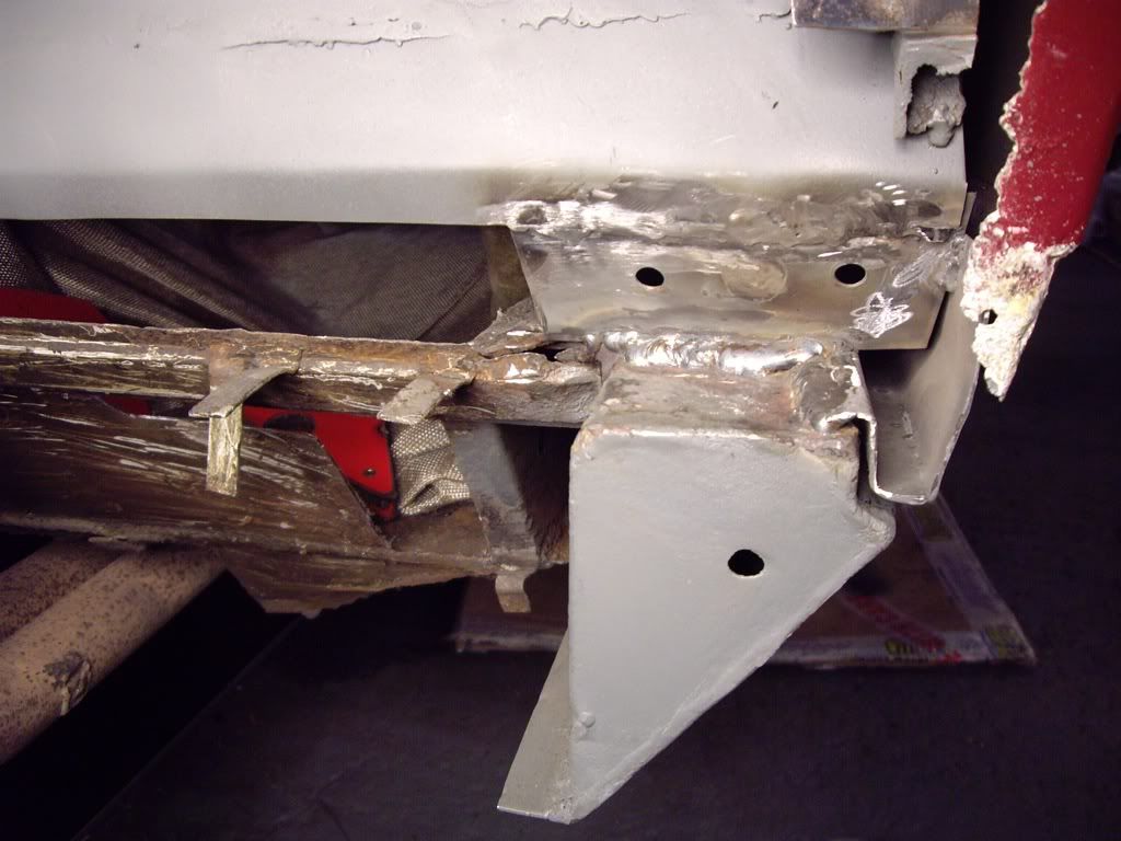
Each new piece is painted on the rear with zinc weld-through primer and the holes are there so I can waxoyl afterwards.
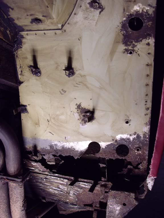
The section below the jacking point has an ugly patch over it, and the area is a bit bent. I think this is mostly due to the bad positioning of two-post jacking pads. The patch is not that obvious here:
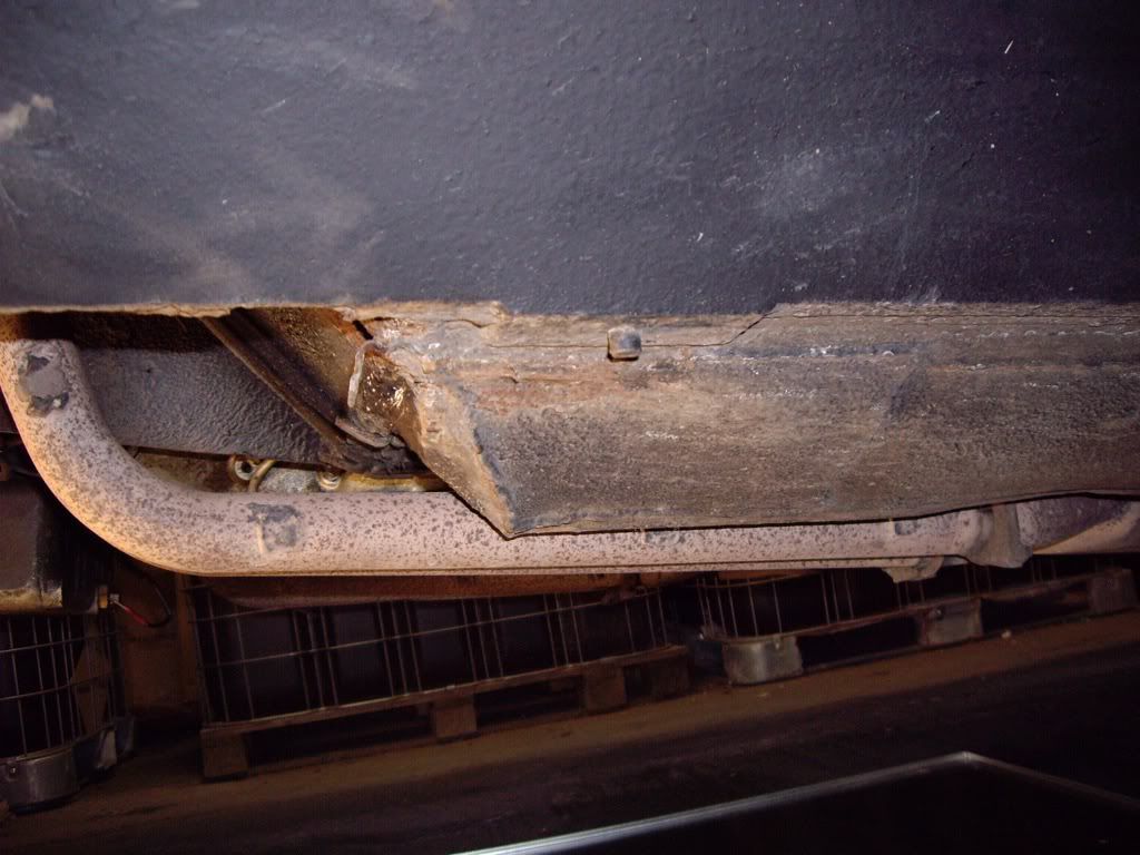
..but here it is being removed:
 |
|
| Back to top |
|
|
|
|
You cannot post new topics in this forum
You cannot reply to topics in this forum
You cannot edit your posts in this forum
You cannot delete your posts in this forum
You cannot vote in polls in this forum
|
|

