 |
LagondaNet
|
| View previous topic :: View next topic |
| Author |
Message |
Mitrovic

Joined: 19 Nov 2007
Posts: 627
|
 Posted: Sat Mar 05, 2011 7:28 am Post subject: Posted: Sat Mar 05, 2011 7:28 am Post subject: |
 |
|
| Great pictures, thank you for sharing! |
|
| Back to top |
|
 |
jonc
Joined: 21 Sep 2010
Posts: 584
Location: Cheshire, UK
|
| Posted: Tue Mar 08, 2011 7:48 pm Post subject: |
|
|
I am now spending a bit of time on the heater control. The controls and wiring need to be in a reasonable state before the car goes to David Marks for its heater upgrade.
The heater control on the car was damaged. The mounting onto the binnacle was broken and because of this (and a missing plastic peg) it didn't click from one setting to another. There was also evidence that the switch had been getting hot.
I have sourced a replacement 'new old stock' AC Delco control assembly which needs taking apart to fit on the binnacle. Here is my old one on the left, and the new one on the right:
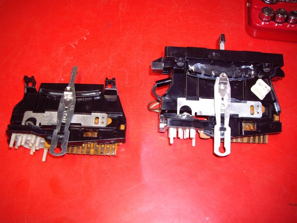
The heater control assembly includes the rotary temperature control and high-temperature switch (inside a black tube). You can also see the heat damage on switch of the old one:
The lever on the new one is slightly different - it is a bit thinner. I considered using the lever off my old control, but the little stainless-steel spring which makes the 'click' is thicker on the new one, so I am keeping it with its smaller knob.
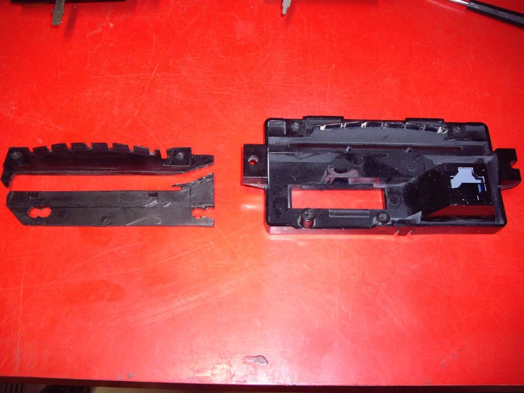
Now, the piece of plastic which holds the control to the binnacle is broken on my car, so I need the one off the new part. At this point I discover that AML have cut down the AC Delco mounting to just the bit which supports the slider control. Here's the difference:
 |
|
| Back to top |
|
|
jonc
Joined: 21 Sep 2010
Posts: 584
Location: Cheshire, UK
|
| Posted: Tue Mar 08, 2011 7:58 pm Post subject: |
|
|
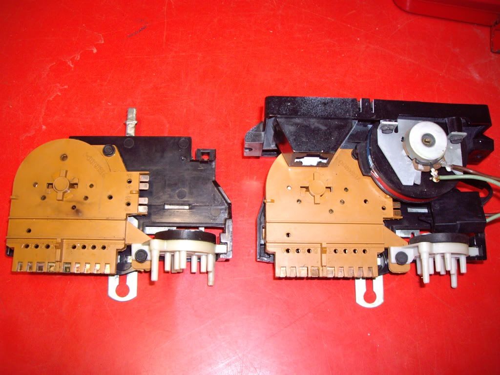
Since my replacement part is actually older than the one it's replacing, I disassemble the switch to check the contacts. Here's what I found:
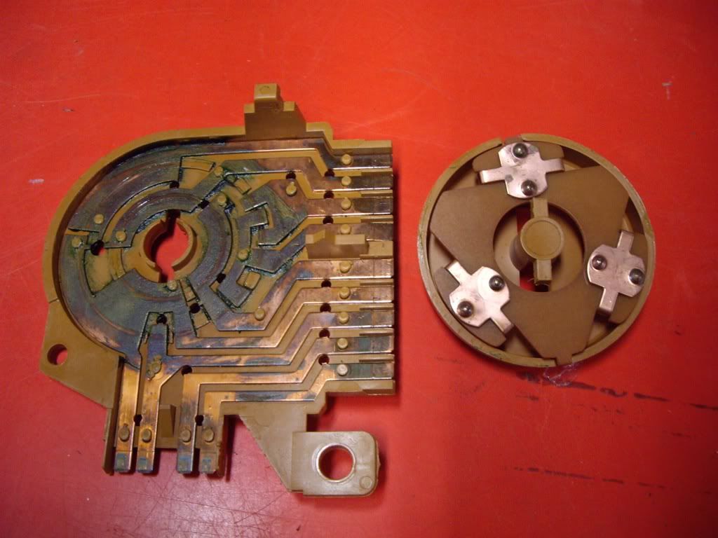
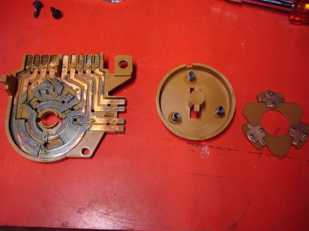
The grease used has caused corrosion of the copper contacts.
I used an ultrasound bath and cleaning solution, plus an bit of a scrub on the stubborn parts and eventually it looked like this:
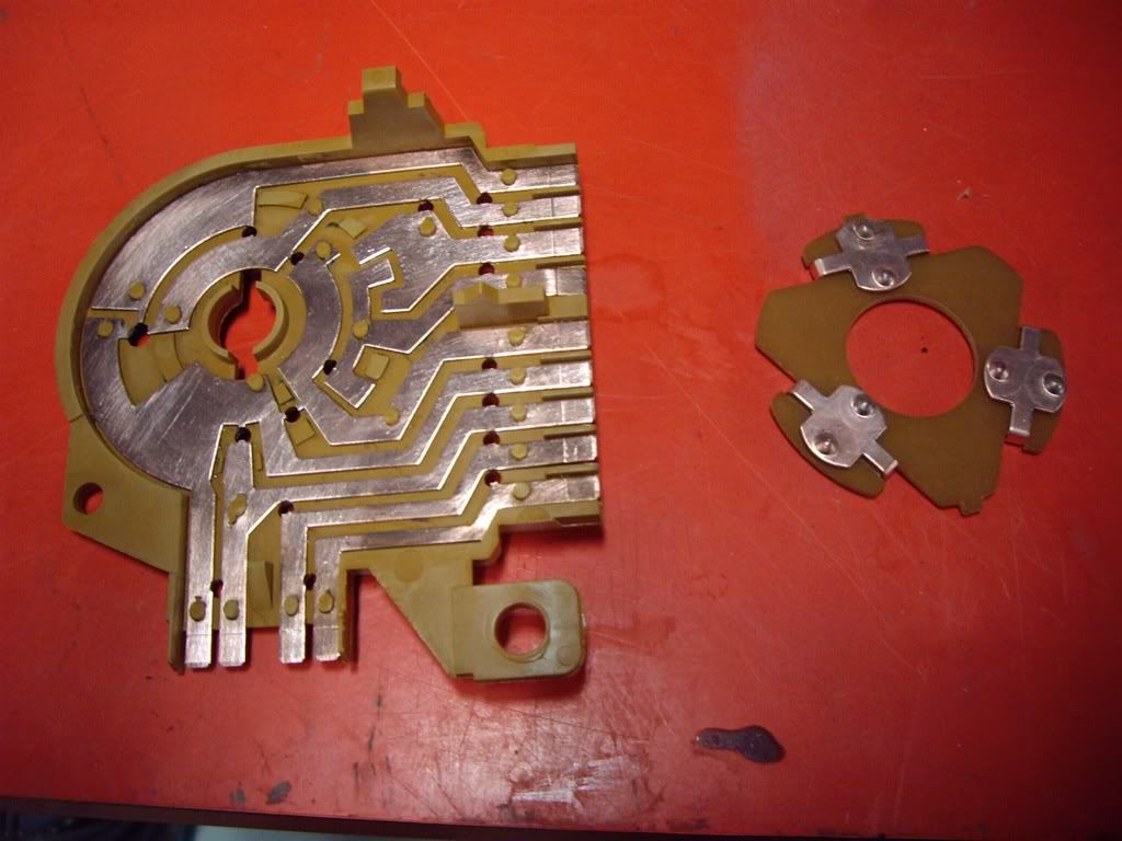
I applied some contact grease and reassembled.
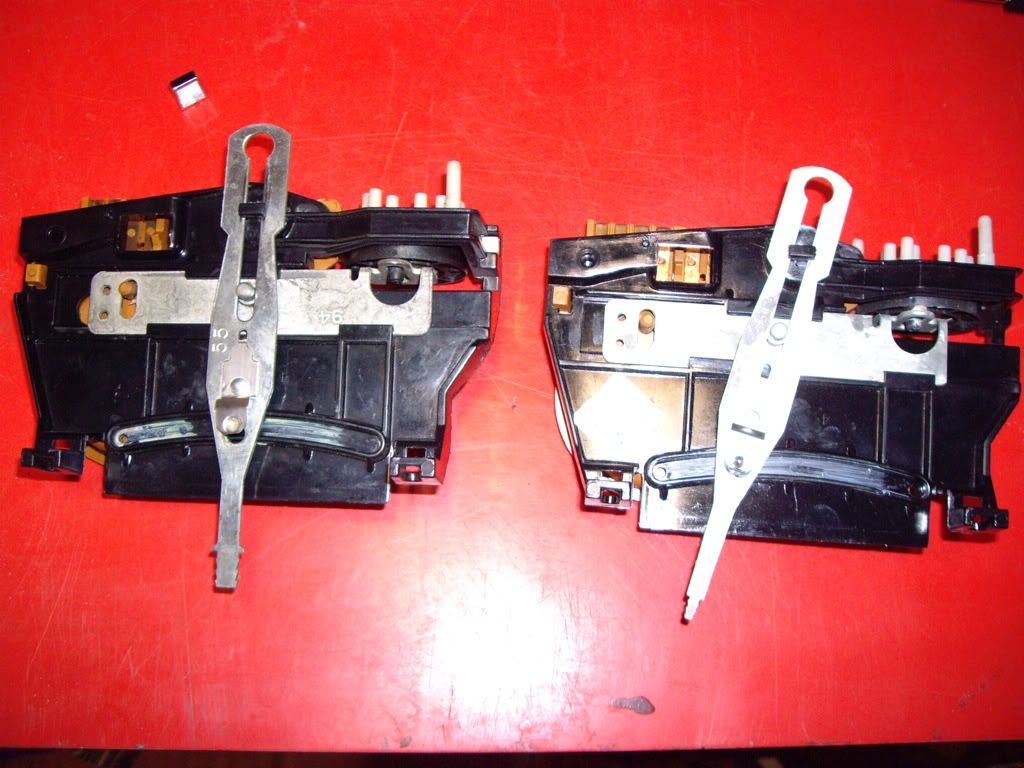
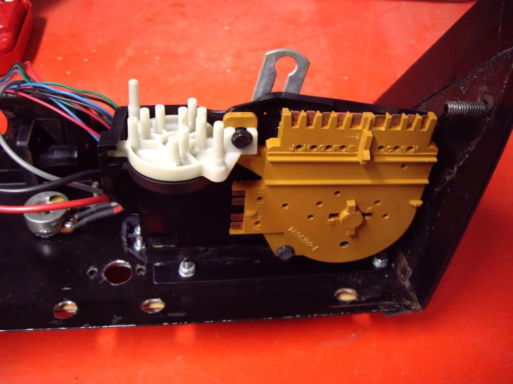
The vacuum switch was a bit stiff since its grease had hardened. I didn't really want to take it apart, so squirted some WD40 into it. This loosened the grease, but made it squeak so I had to take it apart! Here is what it looks like inside:
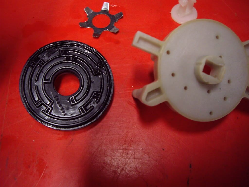
A quick smear of grease on the smooth face and it went back together. I won't be using the vacuum control off this, but I want the slider action to be good. |
|
| Back to top |
|
|
jonc
Joined: 21 Sep 2010
Posts: 584
Location: Cheshire, UK
|
| Posted: Tue Mar 08, 2011 8:10 pm Post subject: |
|
|
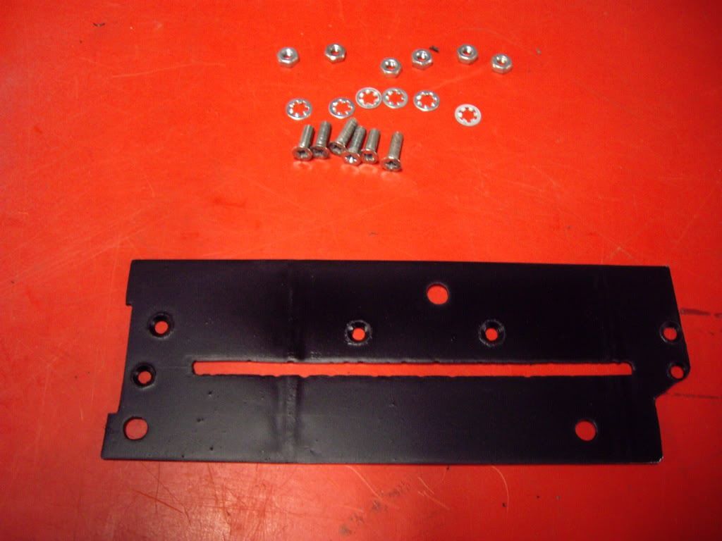
Now on to the slider bracket. The bracket fitted to my car had broken since it was very weak, having had most of the original AC Delco moulding cut off it due to the limited space in the binnacle. My solution is to use slightly more of the plastic to give more strength, but mount this on a metal plate to line up with the three mounting studs on the binnacle. The bracket is cut and shaped with Dremel and file.
Here is my plate, one face already painted. The big holes are for mounting to the binnacle, and the small ones the plastic bracket:
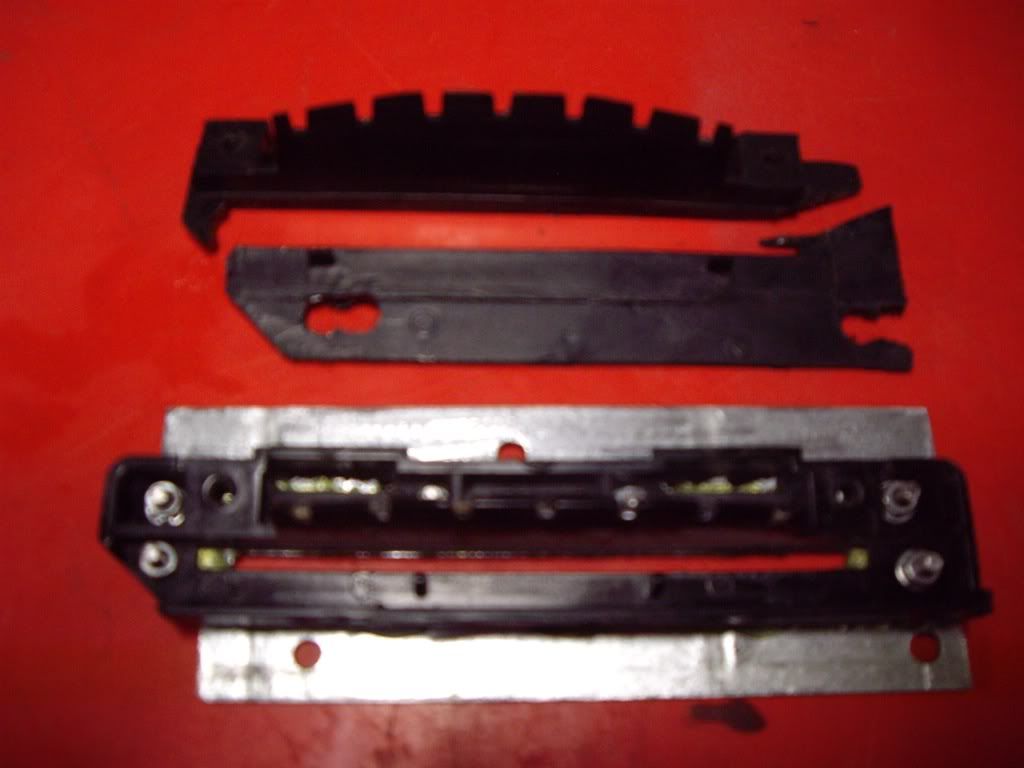
It fixes to the trimmed-down plastic piece with six M3 machine screws which are countersunk into the metal plate. The two pieces are also glued together to give the whole thing more strength. Old and new shown here:
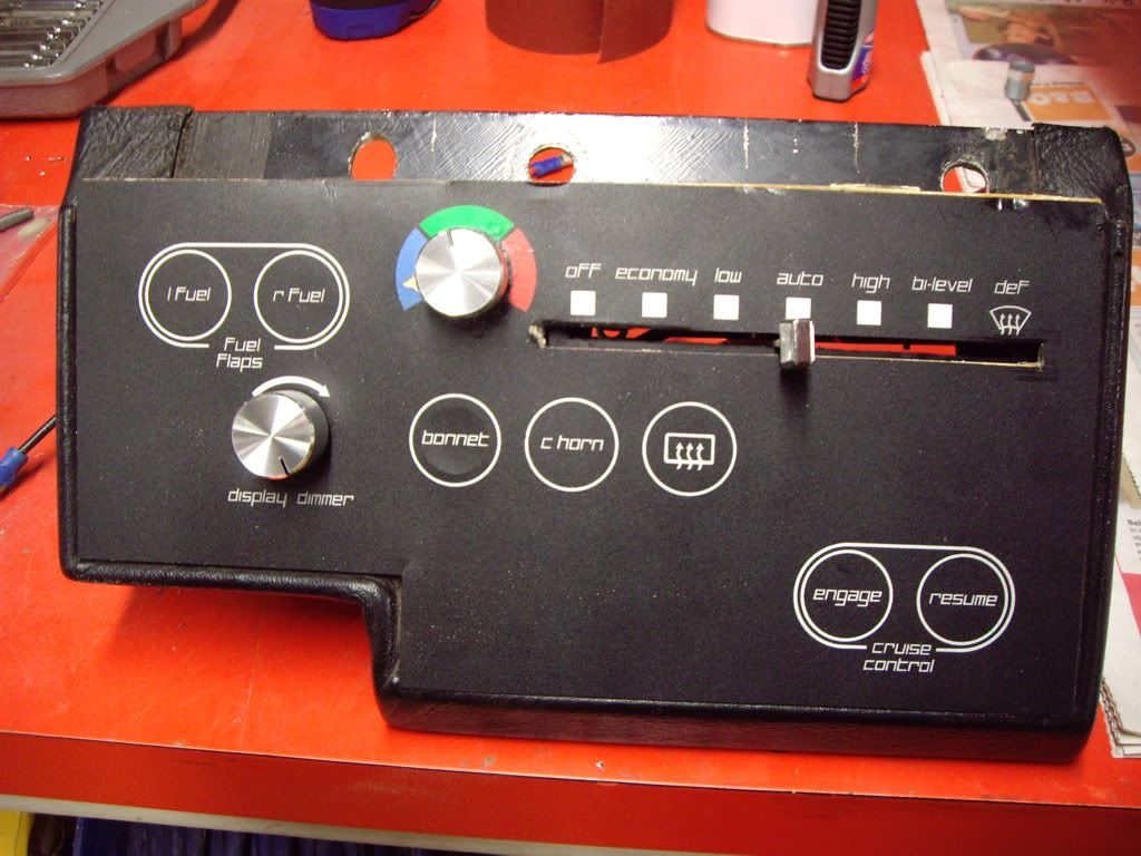
Finally I painted the remaining bare metal. It could then be fitted to the binnacle. Three M4 nuts with star washers secure it:
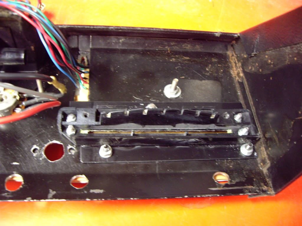
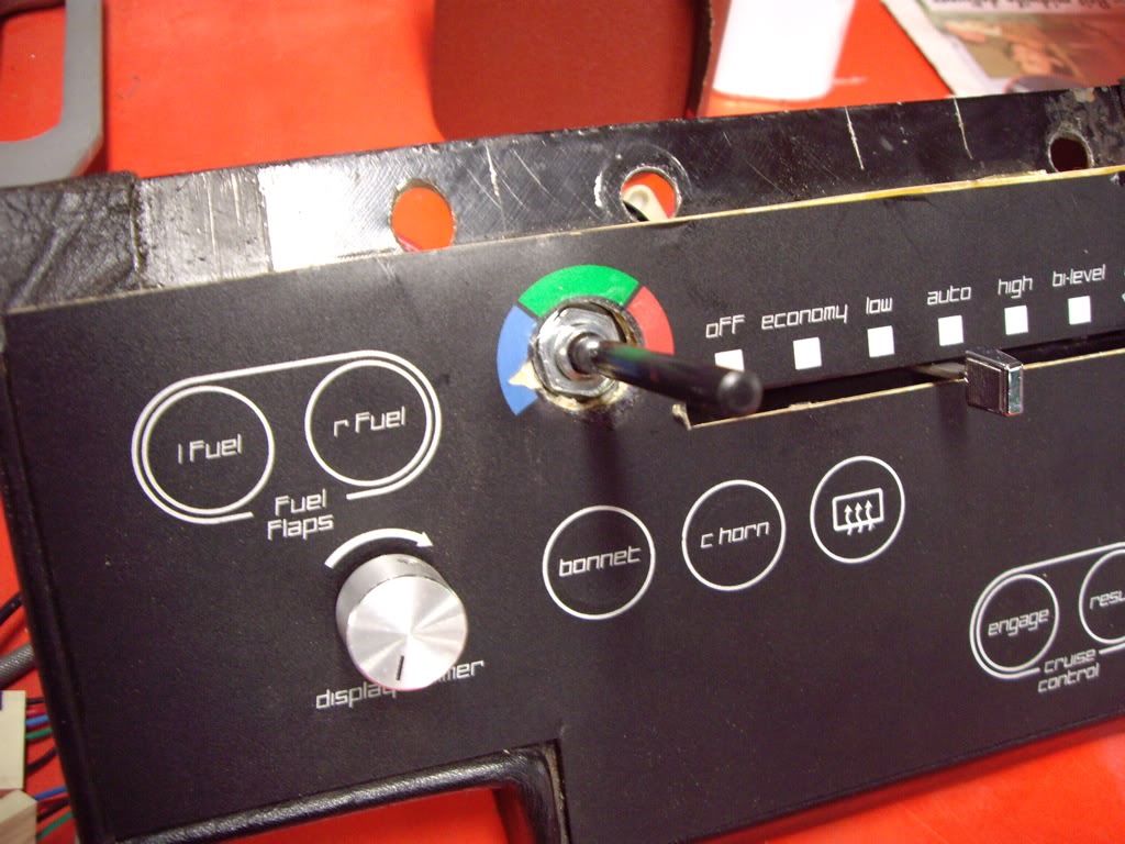
And finally the control fitted:
Total time, about six hours. |
|
| Back to top |
|
|
jonc
Joined: 21 Sep 2010
Posts: 584
Location: Cheshire, UK
|
| Posted: Sat Apr 09, 2011 10:58 am Post subject: |
|
|
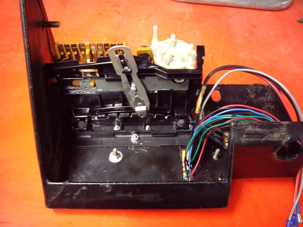
Final part of this - the temperature control.
Since the car is having the David Marks heater upgrade, the control is different to the one from the AC Delco unit. David has kindly provided me with some photos and so I have fitted the new control in advance of the car going to him.
Originally it was mounted on a piece of leather so I have done the same.
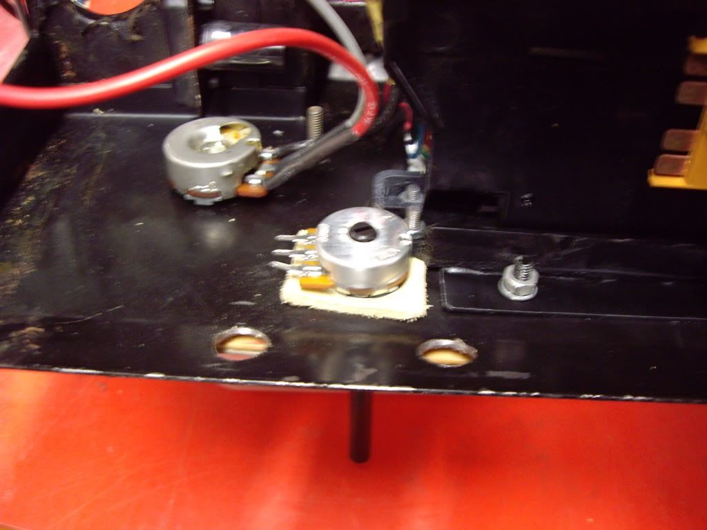
The new control is held in place with a nut rather than the flimsy arrangement of the original one. When I got my car there was a switch in place of this control with a very messy enlargement of the hole. I tidied this up and mounted the new control. I have also fitted new knobs which came from RS Components.
 |
|
| Back to top |
|
|
jonc
Joined: 21 Sep 2010
Posts: 584
Location: Cheshire, UK
|
| Posted: Sat Apr 09, 2011 11:44 am Post subject: |
|
|
Now on to the gearbox loom. In an earlier installment I said the plug was detached from the gearbox and the inhibit circuit was bypassed by grounding the wire which goes down to the gearbox. The plug didn't actually fit on the gearbox, and its wiring didn't match the loom up the bulkhead, and it was connected with cheap non-original crimps and so I thought it was non-original and related to the gearbox being changed for a recon one some years ago.
Here is the plug I removed the car:
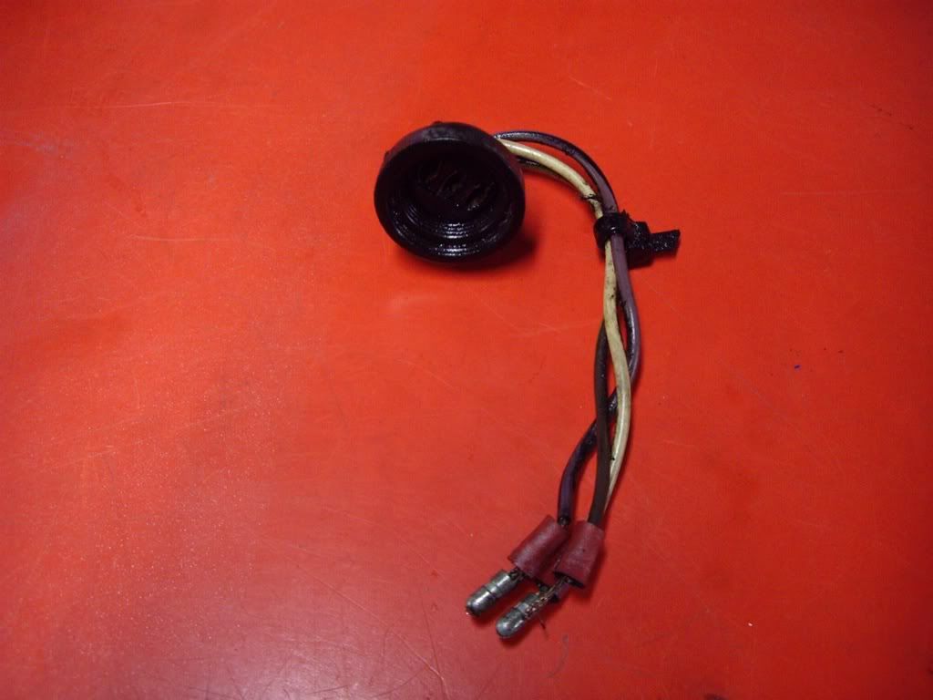
And here is the replacement off a Lagonda from Puddleduck:
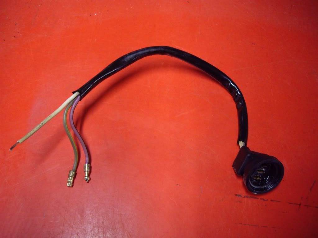
Hmm.. I thought mine was non-standard since the wir colours were different, but actually I think it is because it is a Mopar part. The one from Puddleduck actually fits on the gearbox so I think mine was heat damaged. The replacement had two crimped on bullets and a scotchloc which I presume had replaced the bullet as the wire strands have a black oxide layer on them. Right underneath the car is not a great place for this type of unprotected connector.
I cleaned off the oxidation with a combination of ultrasound bath/acid/DeoxIT D5 and then fitted a new crimp. I also soldered all three crimps to ensure the electrical connection would not deteriorate in future.
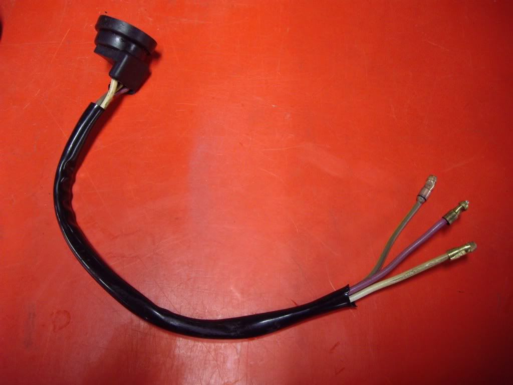
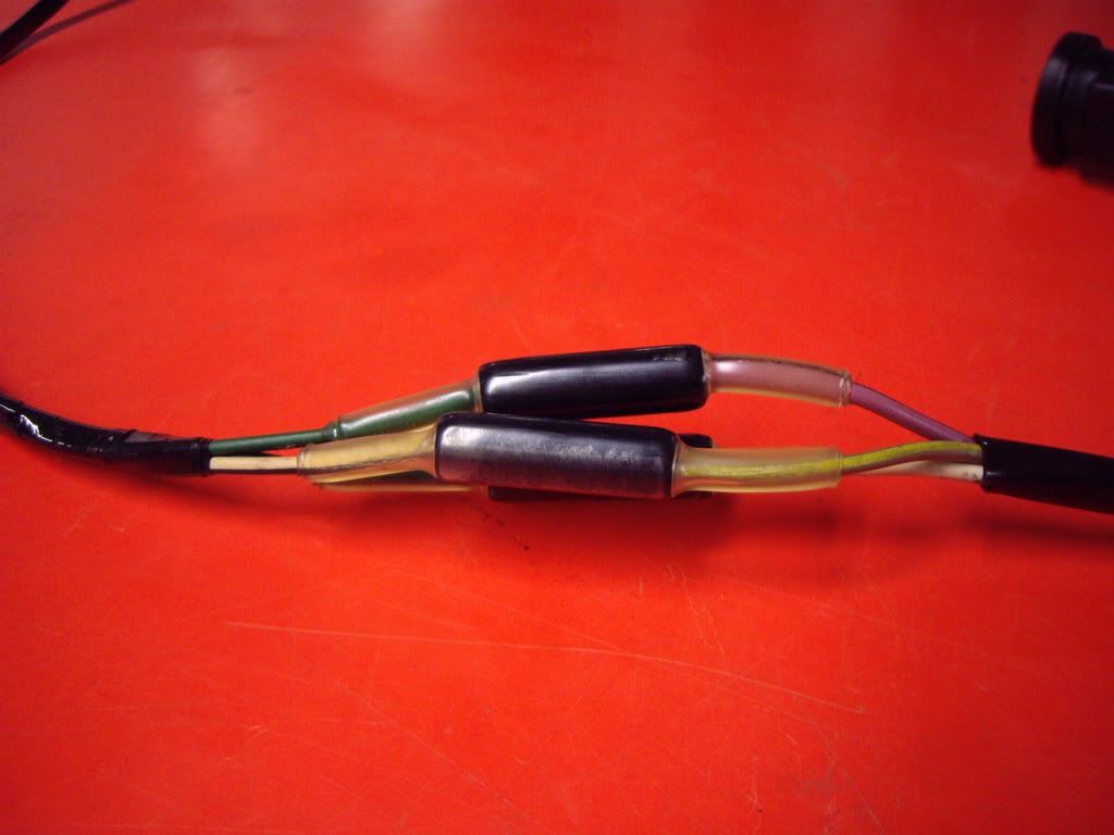
This part connects to a short loom which goes up the bulkhead to a three pin connector (the one I repaired a bit ago). I decided to remove this short loom as it was impossible to properly clean the three pin connector which had been sitting on top of the starter for some time. While the loom was off, I fitted new bullets to the end, cleaned the three pin connector up and retaped it. To ensure there are no connection problems in future, I sealed the three snap-connectors inside clear adhesive-lined heat-shrink tubing.
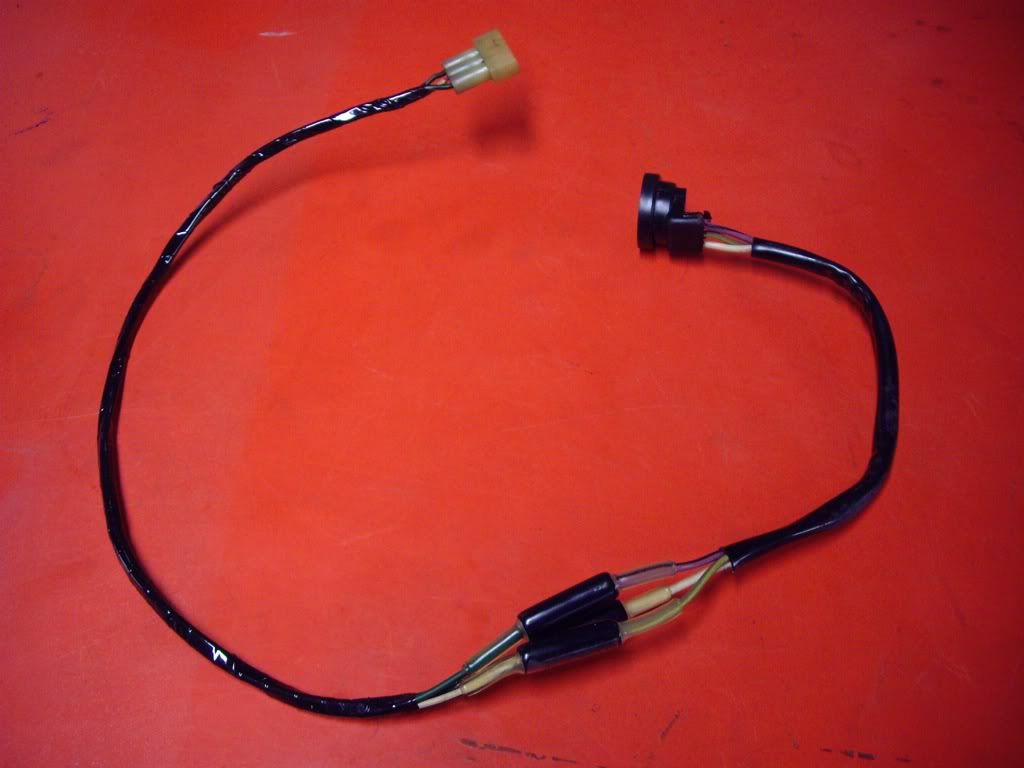
I used clear so in future, anyone can see what is in there without having to take it apart.
So, did it work when I put it all back together..?
No. All the wiring is fine, but there appears to be a problem with the switch.  |
|
| Back to top |
|
|
jonc
Joined: 21 Sep 2010
Posts: 584
Location: Cheshire, UK
|
| Posted: Sat Apr 09, 2011 11:57 am Post subject: |
|
|
Remember I had a leaky sump gasket on the gearbox? Well, I tried tightening the bolts slightly but this didn't fix the leak. So, I ordered a filter kit which is the sump gasket and the oil filter. I also decided I would fit a drain plug as this gearbox doesn't have one, which makes it a messy job when you have to take the sump pan off.
Here I have the sump pan off:
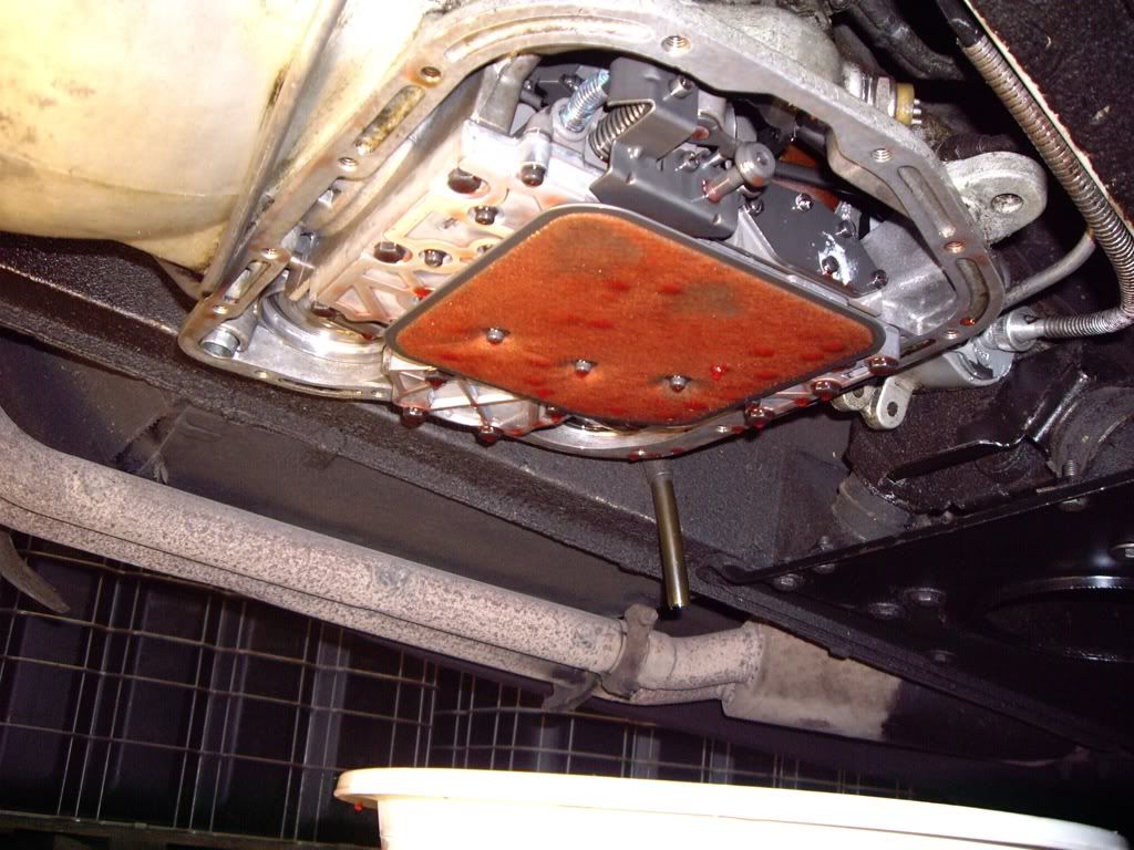
You have to loosen the bolts and break the seal at one end and then let the oil spill out. Mostly in the bowl or on my arm. The red thing is the filter.
Here I have the new sump plug kit; you just drill a hole to fit it. The instructions say to put it in the bottom, but I decided on the side as it protrudes and I don't want it to be ripped off if I ground the car.
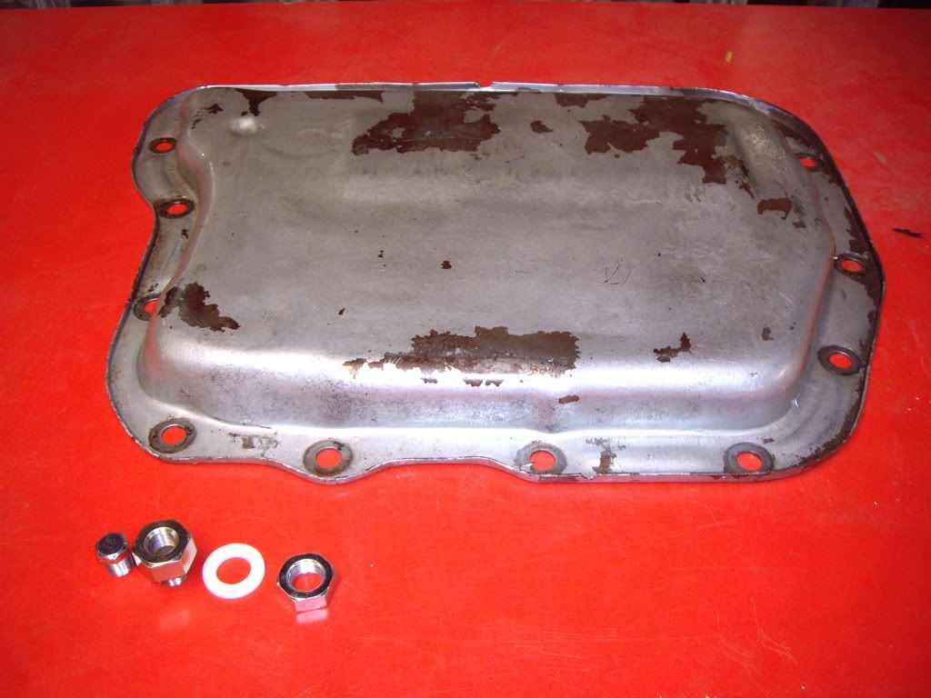
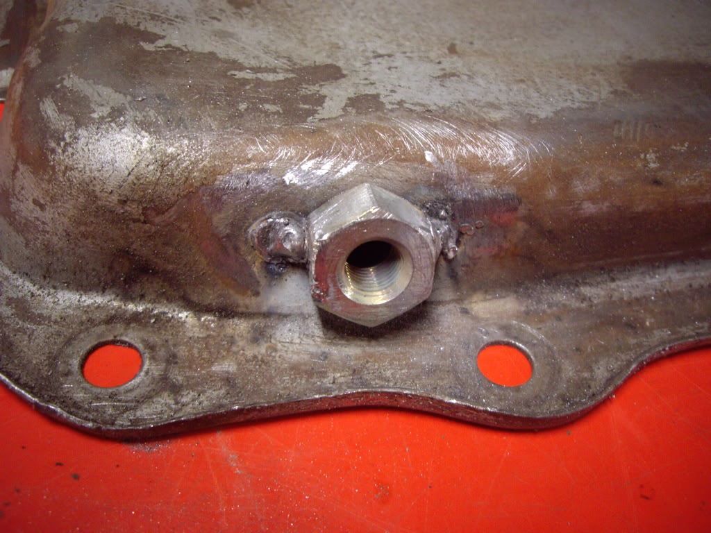
The kit just bolts through the hole and the instructions say you also must use two spanners when undoing it as otherwise you can loosen it. I decided this design could be improved upon, so I have welded it in place with two tacks. This won't come loose now:
Finally, two coats of silver Hammerite and it is ready to go back on:
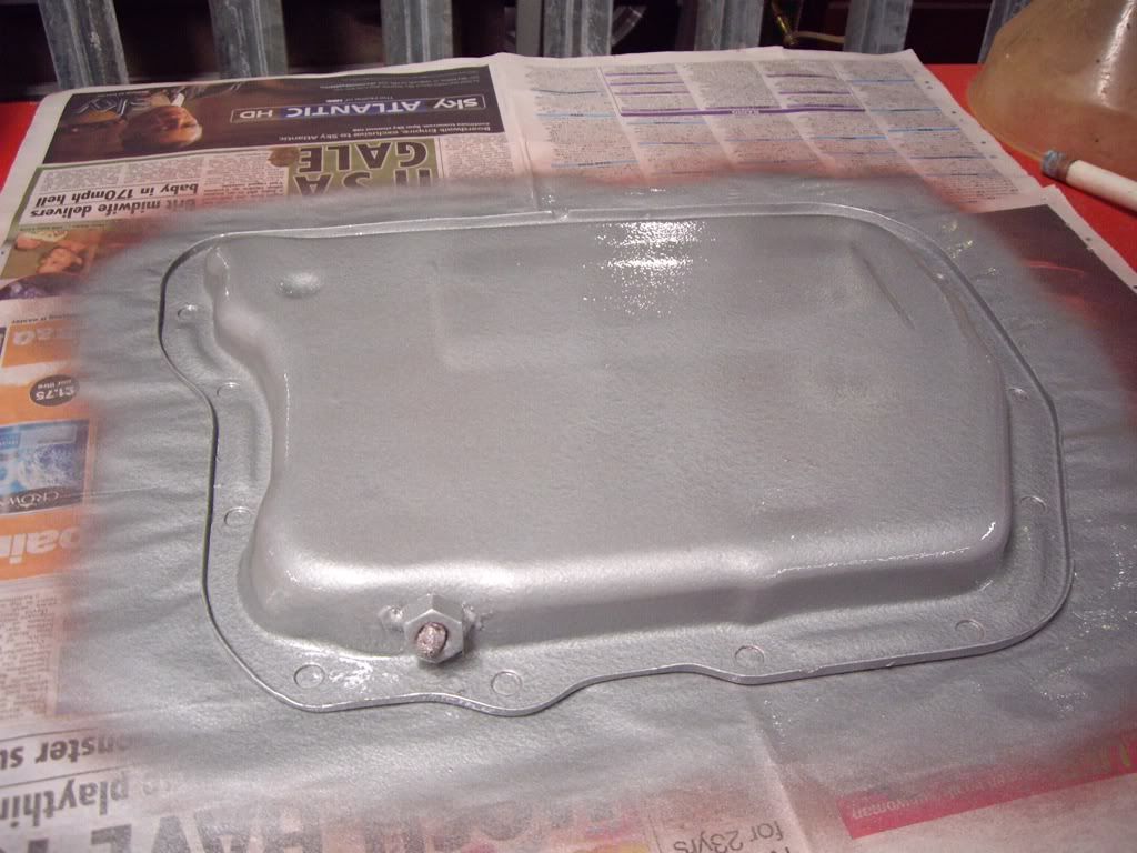
The new gasket is a thinner fibre one which I think will be better than the cork one. However, since it is a pressed steel sump, I use a gasket sealant when refitting. |
|
| Back to top |
|
|
jonc
Joined: 21 Sep 2010
Posts: 584
Location: Cheshire, UK
|
| Posted: Fri May 20, 2011 7:35 pm Post subject: |
|
|
Car was back together enough at this point to go to David Marks to have the heater system upgraded while I was away on holiday. Unfortunately this didn't happen as I tried to organise the transport myself. Oh well..
Back to the work - car has to be ready for the AMOC concours on 22nd May. When the car was driven in anticipation of the trip to Nottingham, I found that there is a fault somewhere which causes interior fuse 11 to blow.
This is about the most complicated single circuit on the car - something which the fuse description in the manual doesn't make clear. Since I suspect the wiring it not great inside the drivers door, and the drivers window is not working (in fact its down!).
Fishing inside the door, this is what is loose inside:
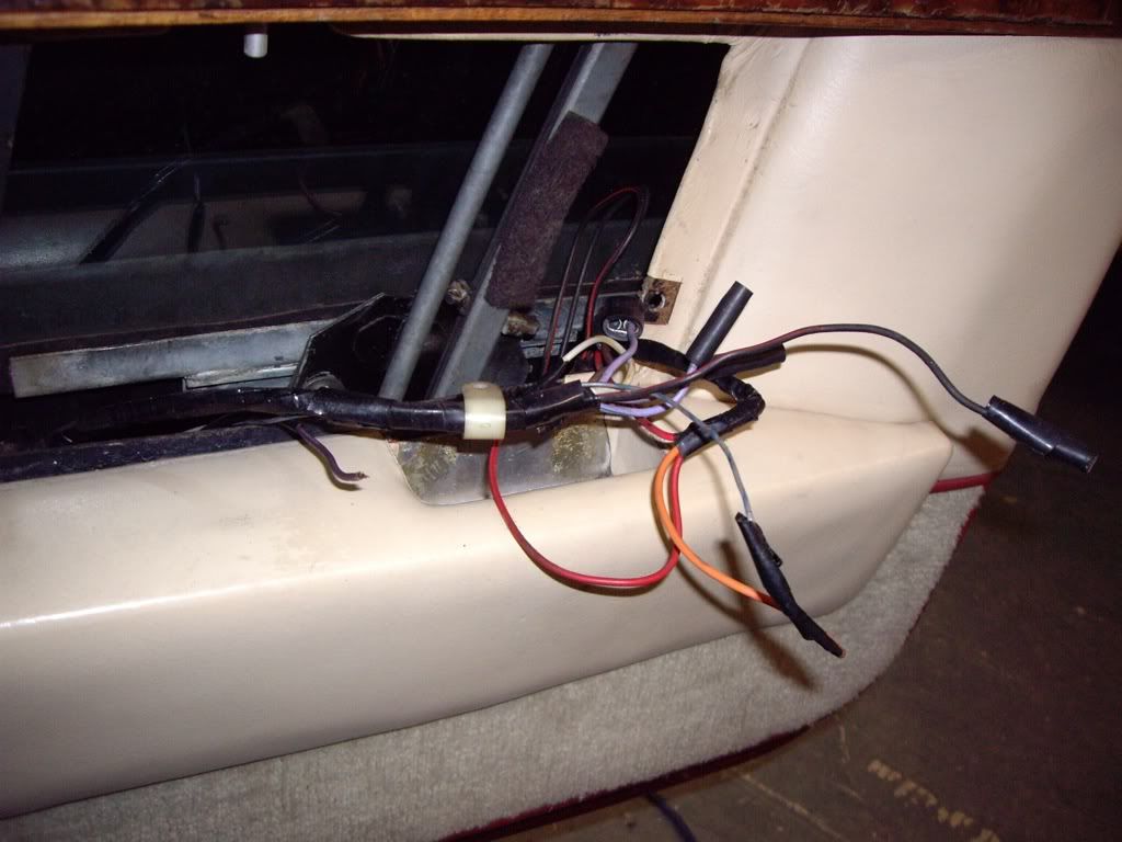
There are a few loose wires, the loom is not secured, there are soldered splices with loose insulating tape on them, and there is a non-original black box:
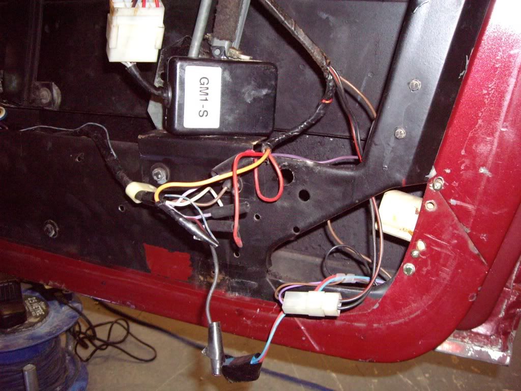
It looks like there is a modification to allow lock and unlock from the drivers door lock. This is instead of the auto-lock and uses an aftermarket lock solenoid with build-in switches to replace the key microswitch (which is still there, but disconnected).
I also found that the auto-lock relay (on the A pillar, drivers side) is dangling, and has a wire disconnected. I fixed this and found it is not reliable as the driver's door pin-switch sometimes does not work properly and so the car will try to lock when the drivers door is open. I took the auto-lock relay out to disable this function, but it could be put back to enable it.
I replace the soldered joints with bullets and snap-connectors - like the original loom connections - and then secure the loom. Good clean of the door card and it goes back together. The fuse still blows |
|
| Back to top |
|
|
jonc
Joined: 21 Sep 2010
Posts: 584
Location: Cheshire, UK
|
| Posted: Fri May 20, 2011 7:55 pm Post subject: |
|
|
So, time to consult the wiring diagram to find out where exactly this circuit goes. Here are my notes, based on the '82 wiring diagram and workshop manual:
157 - green - aircon loom plug (70) - to snap connector (95)
- 173 - green - de-ice micro switch (99)
- 174 - green - A post vent control switch (101)
- 175 - green - aircon programmer plug (102)
234 - green - LH Snap connectors (78 )
- 232 - green - LHF door loom connector (82) - relay coil window dn (84), relay coil window up (85)
- 233 - green - low rad control (79), low washer control (80)
220 - green - connected at loom plugs (73) to rear loom via trans tunnel (not sure if connected?)
- 117 - green - RH bulkhead plug (67) to engine compartment - horn relay
- 116 - green - horn change coil
- 118 - green - relay (60) - vacuum control
- 120 - green - vacuum solenoid (51)
- 449 - green - vacuum solenoid (52)
- 322 - green - via RH bulkhead plug (67) to RH snap connector (129)
- 291 - green - RHF door loom plug (133) - window up + dn relay coils (140/141)
- 323 - green - brake light switch (214)
- 337 - green - econocruise plug (130)
- 324 - green - A pillar loom (134) to hazard sw (135)
+ 371 to dash floods (137)
+ 370 - green - via instrument panel warning light conn (112) to lamp commons (MARKED 307)
??? (MARKED 355) - green - indicator flasher (108)
- 325 (MARKED 324) - green - econocruise relays (125/126)
The feed from the fuse splits into three at the fuse box, so I know the fault is on the 220 wire - of course, the most complex one!
Ahah! This looks like it - the wiring to the vacuum solenoids is melted, and there is a loose wire which is the remains of a suppression capacitor. You can just about see it here:
Here is the bit I chopped out:
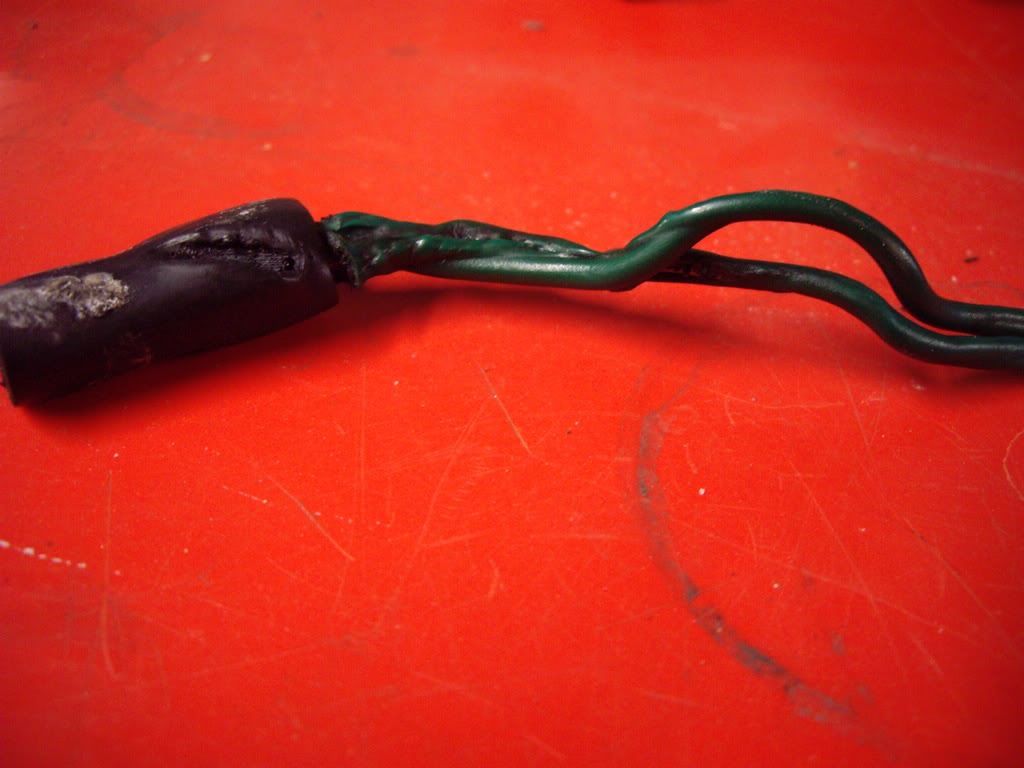
The loom going to the solenoids was not wrapped, and it probably should be, but until I am sure I protect it with spiral wrap.
I test again... and fuse still blows. |
|
| Back to top |
|
|
Arnaud
Joined: 26 Oct 2010
Posts: 101
|
| Posted: Fri May 20, 2011 7:56 pm Post subject: |
|
|
| Pretty Interesting, thank you for sharing Jonc ! |
|
| Back to top |
|
|
jonc
Joined: 21 Sep 2010
Posts: 584
Location: Cheshire, UK
|
| Posted: Fri May 20, 2011 8:21 pm Post subject: |
|
|
So, I need to isolate the fault since I am at a bit of a loss. I have dealt with all the potential faults I can see - replacing damaged loom, missing connector insulating boots etc.
There is a snap connector behind the A pillar footwell finishing panel which has one feed and four wires feeding various bits. By disconnecting these, I find that the problem is with the feed up to indicators and dash warning lights.
So, dash out and here is what I found:
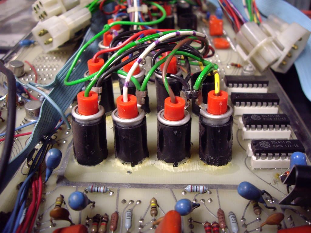
It is not obvious, but look at the right two lamp holders. One has a black wire to the holder and one has a green. The green is a permanent +12v, the black is a ground. And they are touching.
This most likely happened when I replaced the bulbs some time ago. It didn't even occur to me at the time that there was a chance of them touching, or that it would even matter if they did. Really, AML should have applied a hellerman (rubber) sleeve to these ends to stop this.
I found six places on the dash where this could happen so I used loom tape to insulate them. I used this instead of insulating tape since its adhesive would deteriorate over time and it would come loose. I also reglued all the black holders with contact adhesive to keep them in place.
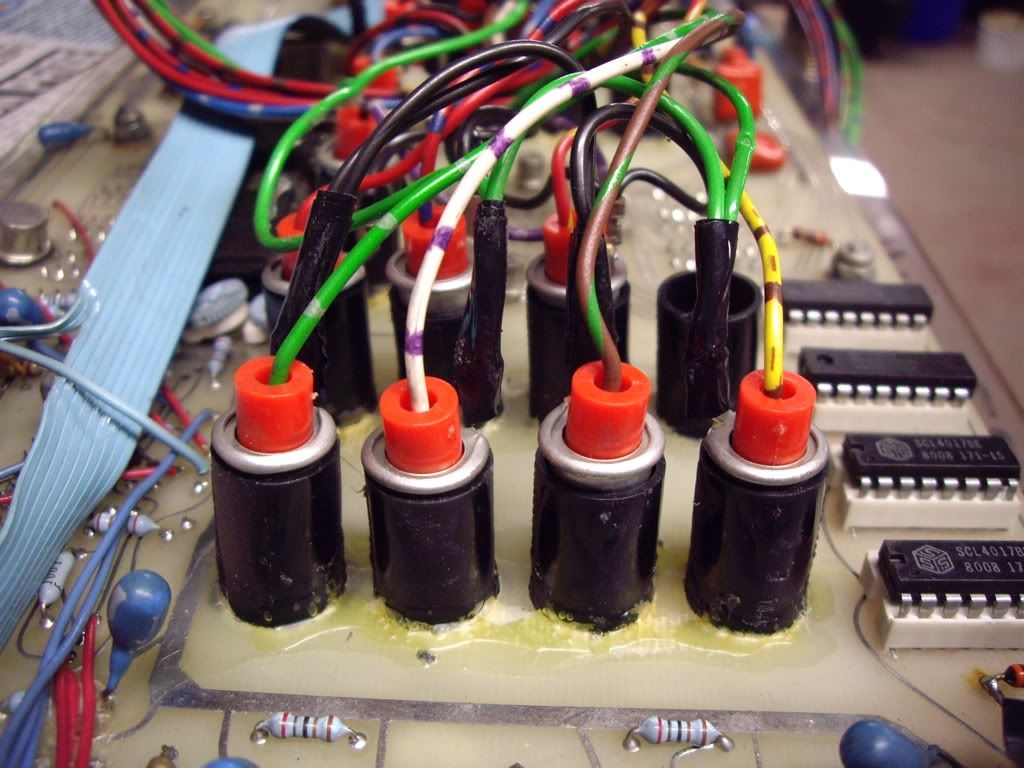
When I reconnect the dash, the circuit is ok. 
Last edited by jonc on Fri May 20, 2011 8:32 pm; edited 1 time in total |
|
| Back to top |
|
|
jonc
Joined: 21 Sep 2010
Posts: 584
Location: Cheshire, UK
|
| Posted: Fri May 20, 2011 8:30 pm Post subject: |
|
|
Thanks Arnaud - I am catching up with a few posts at the moment.
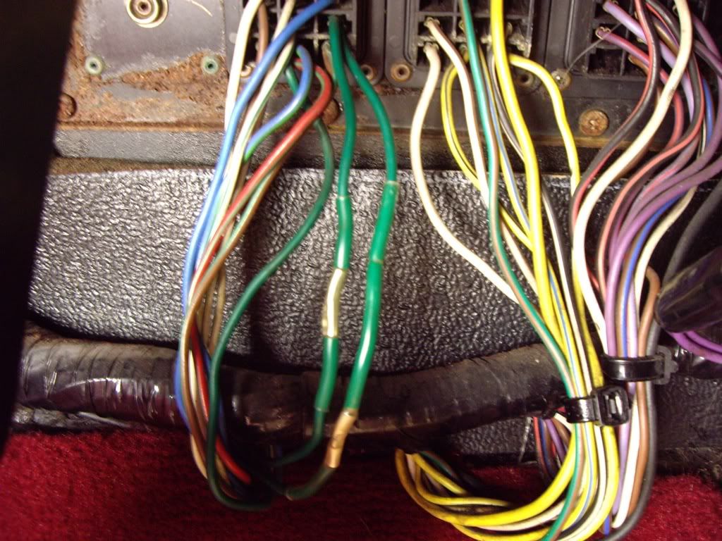
There were a few other places to tidy up, to finish the loom work. Someone has tried to find a fault on this circuit before and has chopped wires in the process:
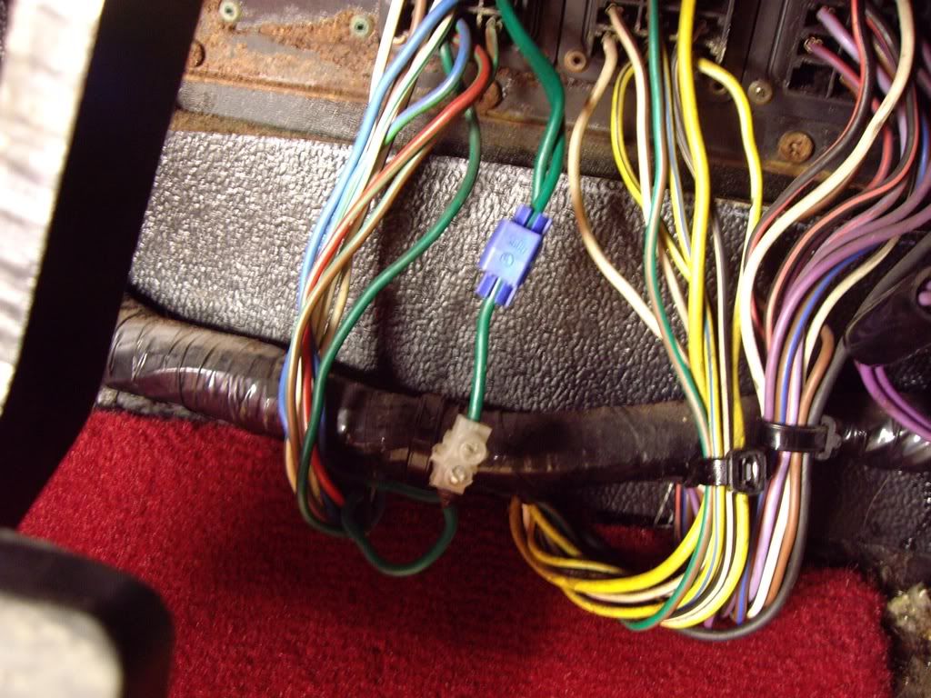
I fixed this with crimp splices and adhesive lined heat shrink so I properly supported the place where the Scotchloc was:
I also took off the passenger bulkhead connector panel to check the state of the connectors:
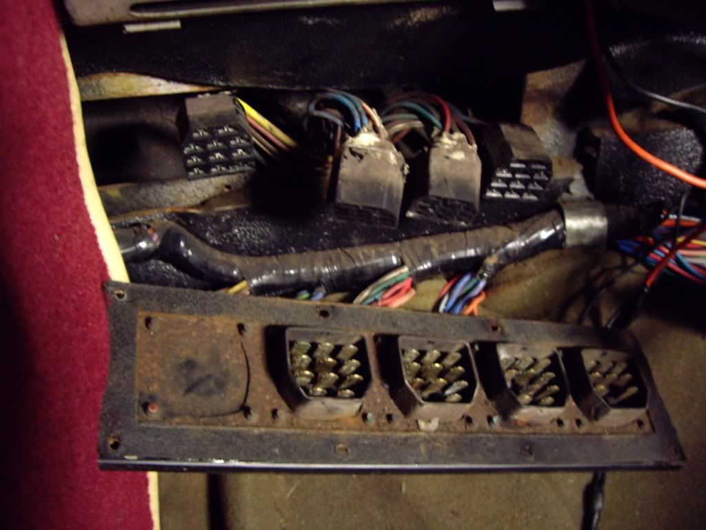
I was pleasantly surprised by the condition but gave all the connections a good clean and a spray with DeoxIT D5 and lube before reassembly. The connectors on the engine side are protected with silicone sealant in the back of the plug connector but water could still get into the connector where it is plugged into the socket.
Reassembly took an entire afternoon as I sheared three of the screws off when removing them, even though I was extremely careful. I had to drill and retap the holes before I reassembled with stainless steel M4 machine screws. |
|
| Back to top |
|
|
Mitrovic
Joined: 19 Nov 2007
Posts: 627
|
| Posted: Sat May 21, 2011 6:47 pm Post subject: |
|
|
| Are you joining us in Dinard? I would like to shake your hand! |
|
| Back to top |
|
|
jonc
Joined: 21 Sep 2010
Posts: 584
Location: Cheshire, UK
|
| Posted: Mon May 23, 2011 9:12 am Post subject: |
|
|
Hi Mitrovic. Unfortunately I will not be there
Now a few jobs under the bonnet. I knew the vacuum advance didn't work so I have now replaced this. It can be done without removing the distributor, but its not good for your back!
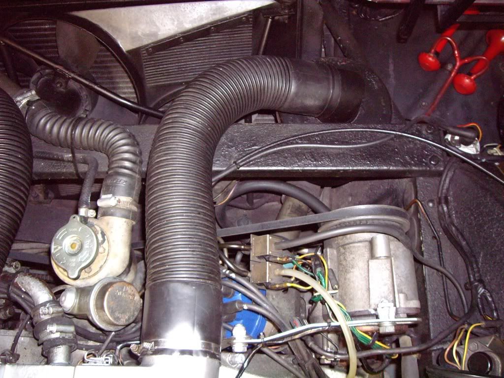
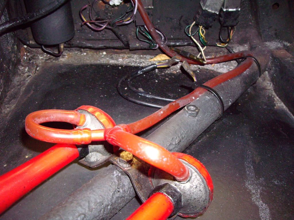
While I was in that area, I remembered that the air pump pipe was leaking. The output from the air pump goes into a metal pipe which joins to a short flexible rubber pipe before going back to a metal one which feeds the air regulator at the front of the engine. This rubber pipe is just push-fitted and had hardened, expanded and slid down the pipe leaving a gap. This meant no air feed to the exhausts, and no positive pressure for the vacuum advance/retard. It also made it a bit more noisy under the bonnet.
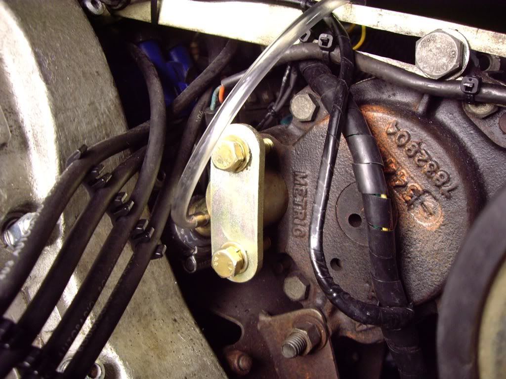
I removed the metal pipes and cleaned and replated them before attaching a new section of hose. I have secured it with stainless Jubilee clips this time and then the complete pipe section can be refitted as one piece, feeding it past the distributor and up from below the air pump. This can all be done without removing or even loosening the air pump.
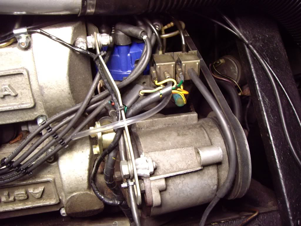
Here you can see the gold end of the pipe which is clamped to the back of the air pump. I also fitted a new piece of clear pipe for the feed to the vacuum solenoids:
And this one better shows how I have protected the loom for the solenoids:
 |
|
| Back to top |
|
|
jonc
Joined: 21 Sep 2010
Posts: 584
Location: Cheshire, UK
|
| Posted: Mon May 23, 2011 7:40 pm Post subject: |
|
|
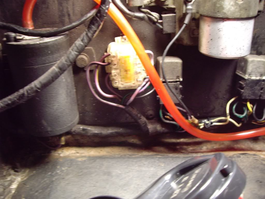
Now to fit the town horns which were missing. Not only were they missing, but so was the relay. I suspect it had been pinched to replace one of the lights ones at some point:
There is a chocolate block connector joining the wire for the air horns so they are permanently connected. The rest of the wires are disconnected so there is no connection for the dash lamps. Fortunately, all the wires are still there.
The new impulse relays look different to the original ones, and I wanted to put an original one here, so I have substituted a modern replacement for the heated rear window one which is hidden behind the back seat.
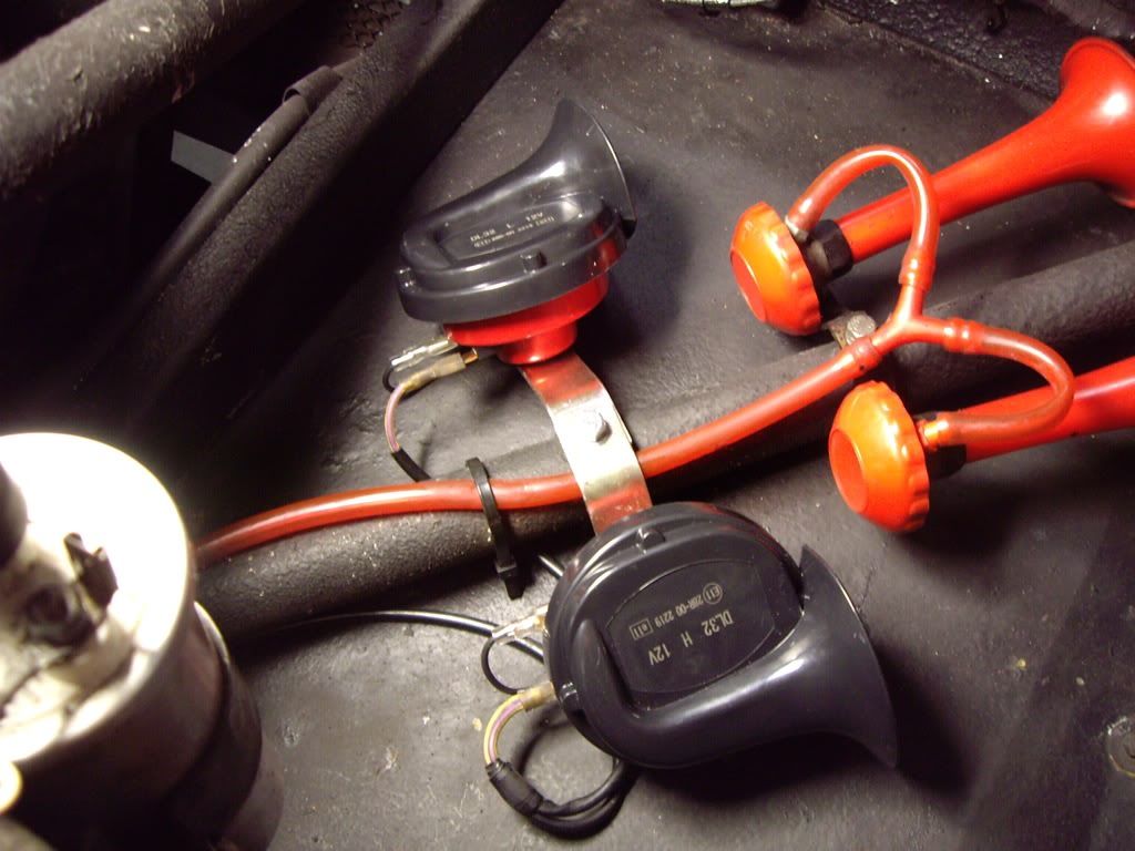
Finished job:
and the horns are just some generic ones, with the brackets bent to match the original bracket. I also had to make up some short earth wires since the horns need a +12v and a ground feed. These connect onto the bolt which mounts the horn:
 |
|
| Back to top |
|
|
|
|
You cannot post new topics in this forum
You cannot reply to topics in this forum
You cannot edit your posts in this forum
You cannot delete your posts in this forum
You cannot vote in polls in this forum
|
|

