 |
LagondaNet
|
| View previous topic :: View next topic |
| Author |
Message |
jonc
Joined: 21 Sep 2010
Posts: 584
Location: Cheshire, UK
|
 Posted: Wed Dec 16, 2015 4:04 pm Post subject: Posted: Wed Dec 16, 2015 4:04 pm Post subject: |
 |
|
So much to update on.
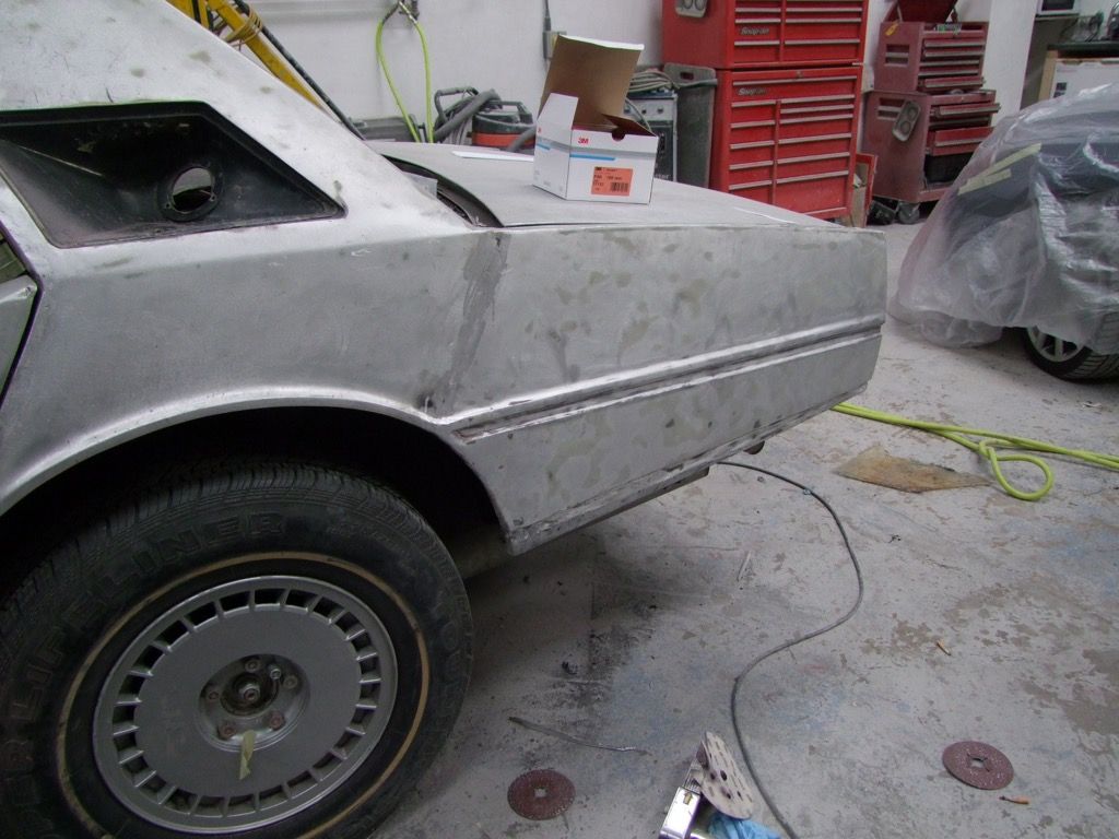
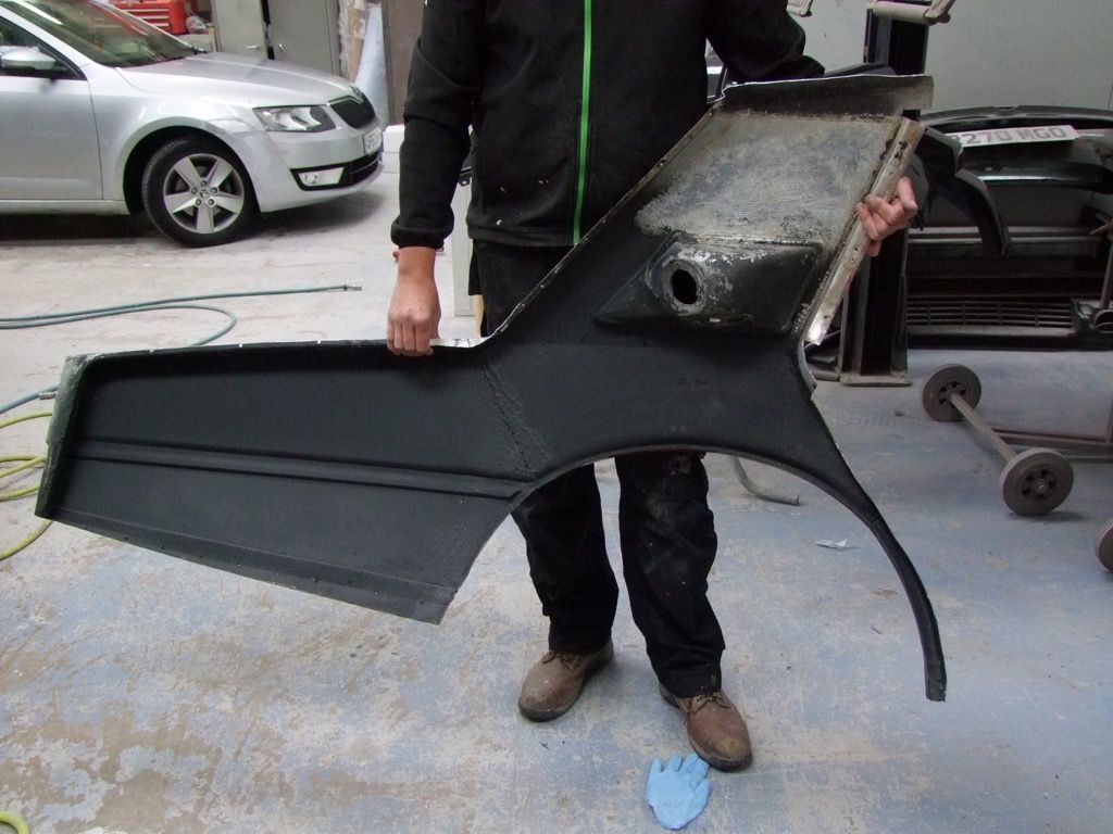
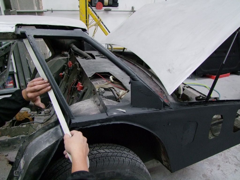
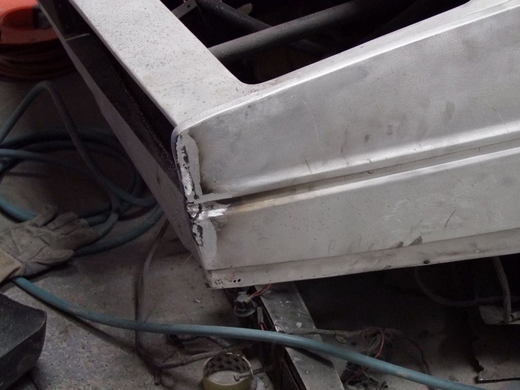
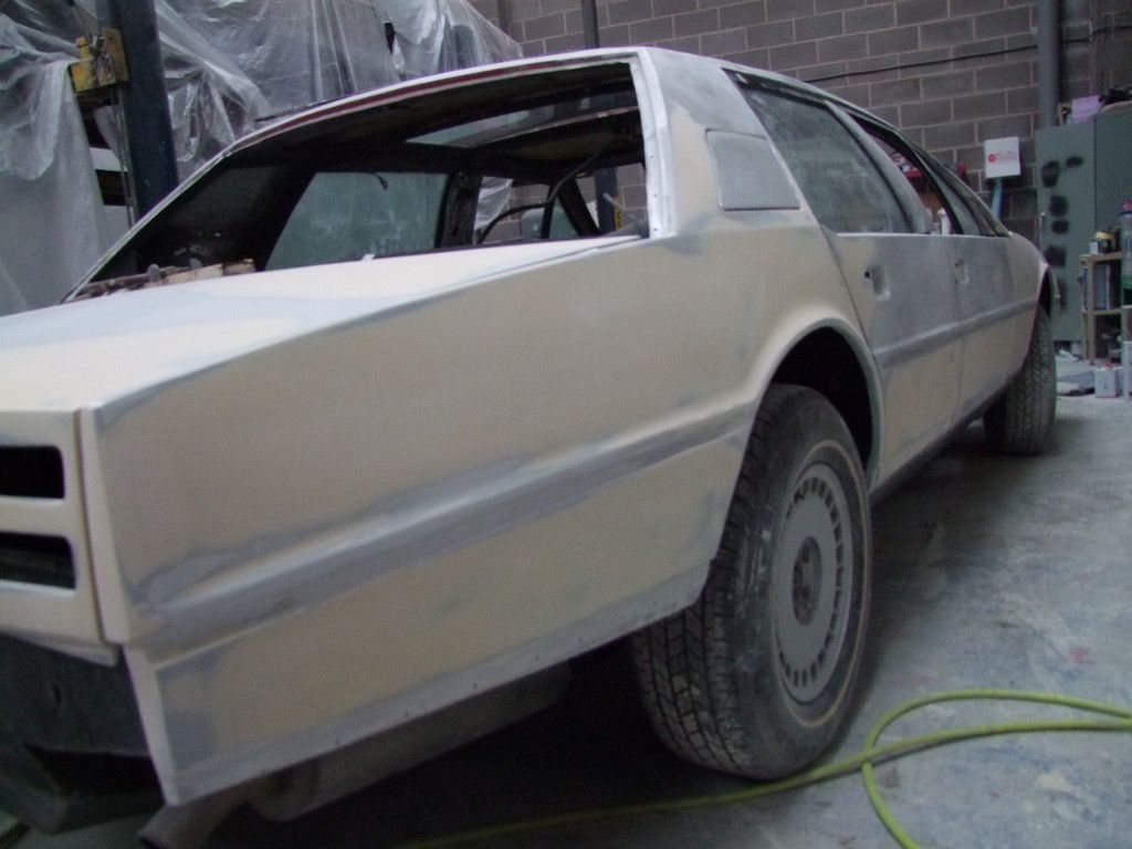
We have a replacement rear wing, but remember there was a problem because it is a different shape at the rear to a standard one:
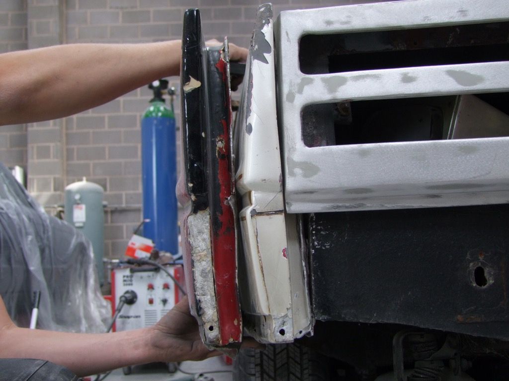
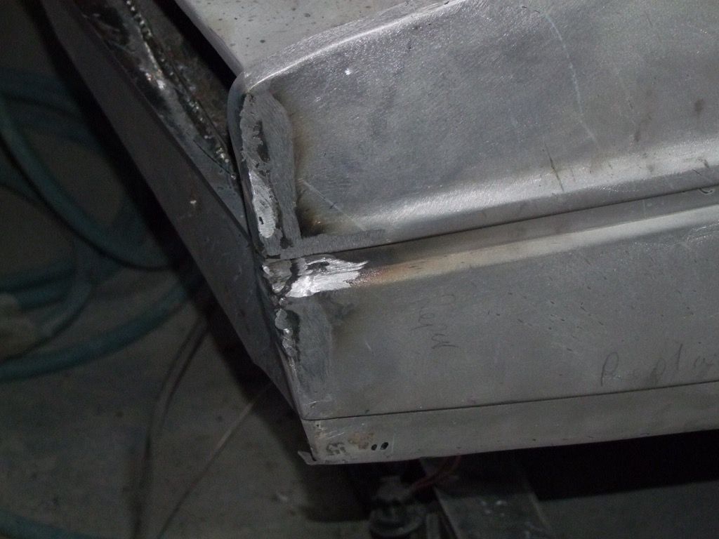
The rear edge is different, and so the shape towards the rear of the wing as well. The solution to this is to only replace the metal we actually need to:
The wing is made up of three parts with the rear remaining original. Now to start welding it together.
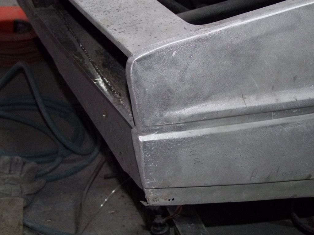
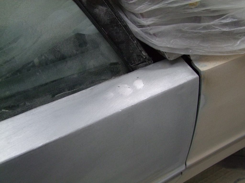
Since this is a hand-built car with hand-made panels, the size needs adjusting at the front edge to make the gap correct. It is cut off and re-welded:
Gap is now looking good:
The wing is complete:
just the back to paint:
 |
|
| Back to top |
|
 |
jonc
Joined: 21 Sep 2010
Posts: 584
Location: Cheshire, UK
|
| Posted: Wed Dec 16, 2015 4:24 pm Post subject: |
|
|
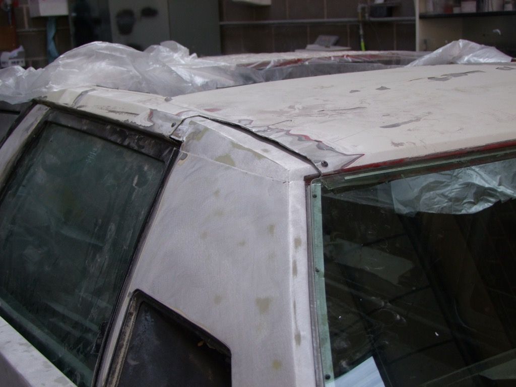
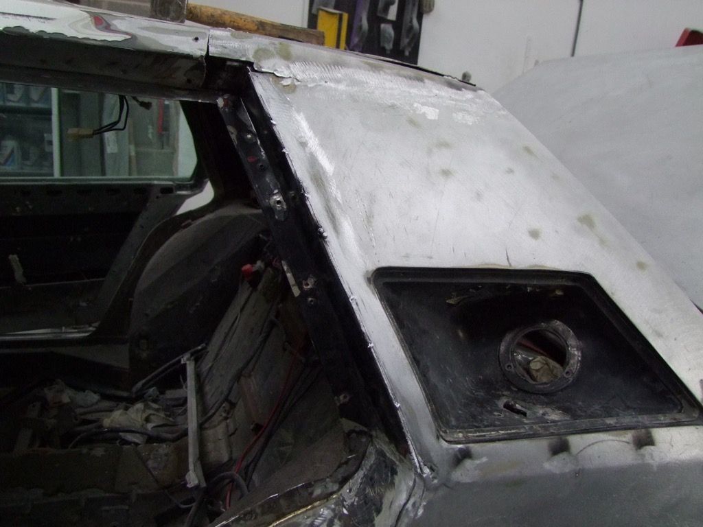
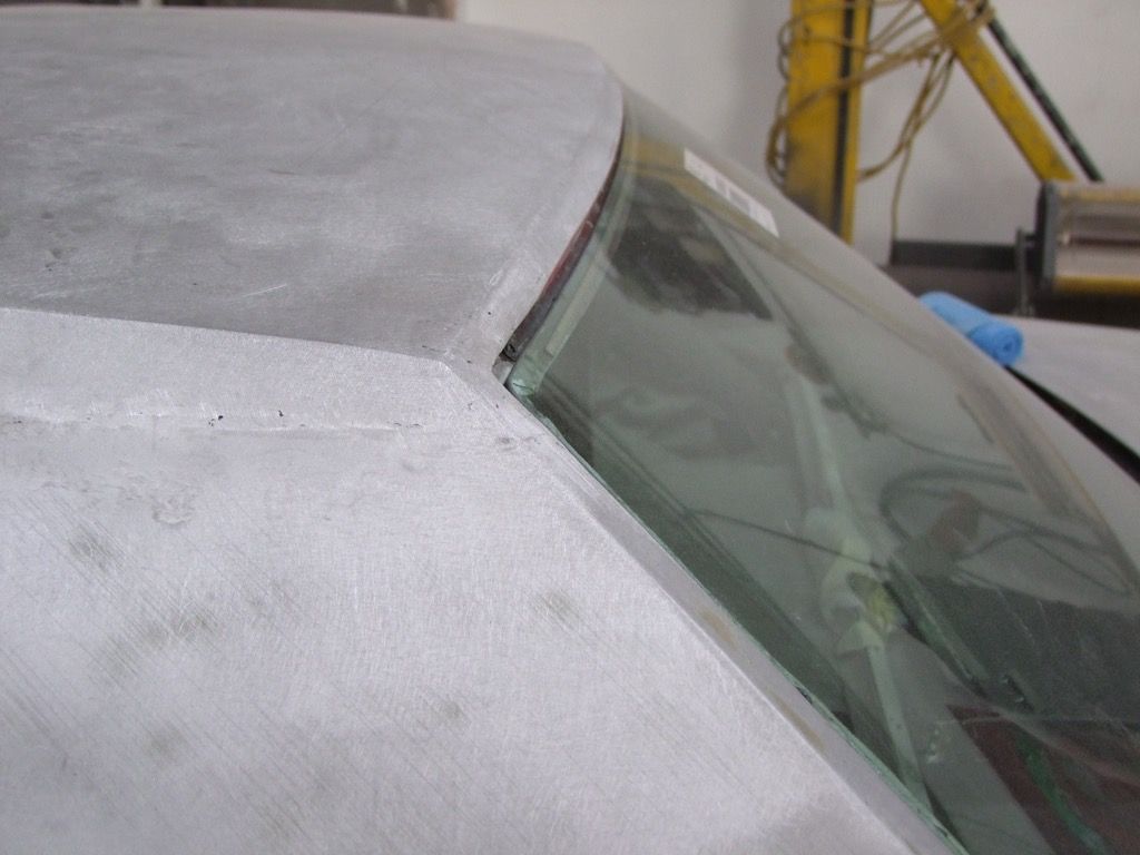
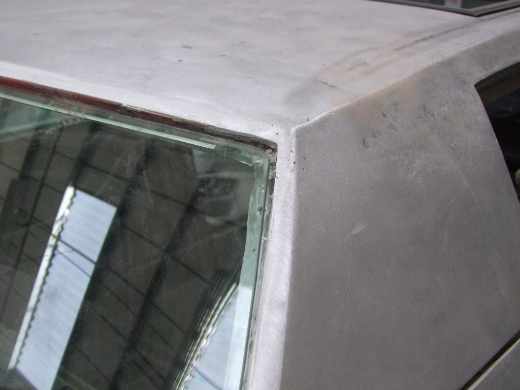
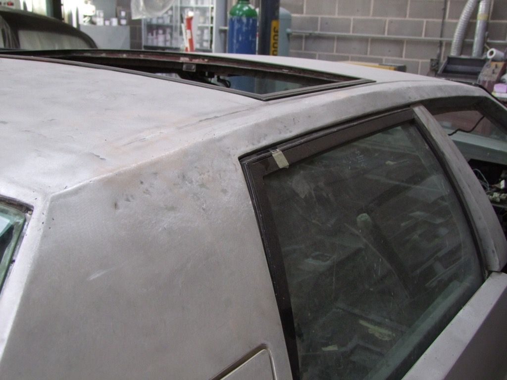
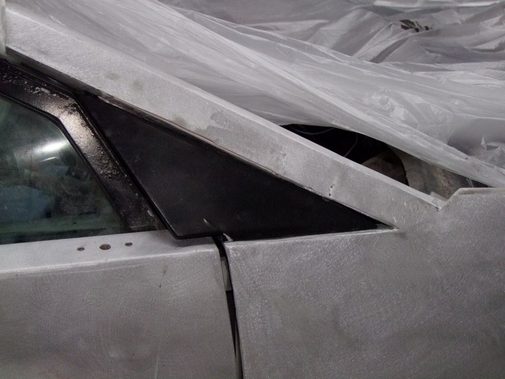
Before the wing can be refitted, the shape of the roof must be checked for true by measurement and also against the glass:
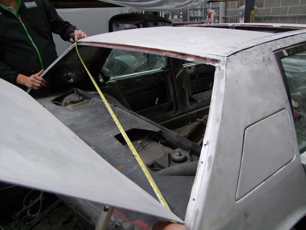
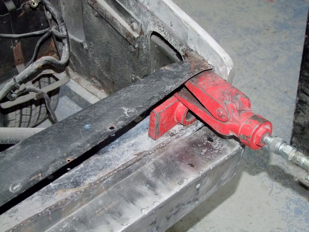
Cuts are also made to allow the opening up of the metal where it has shrunk. These will be re-welded once at the correct shape.
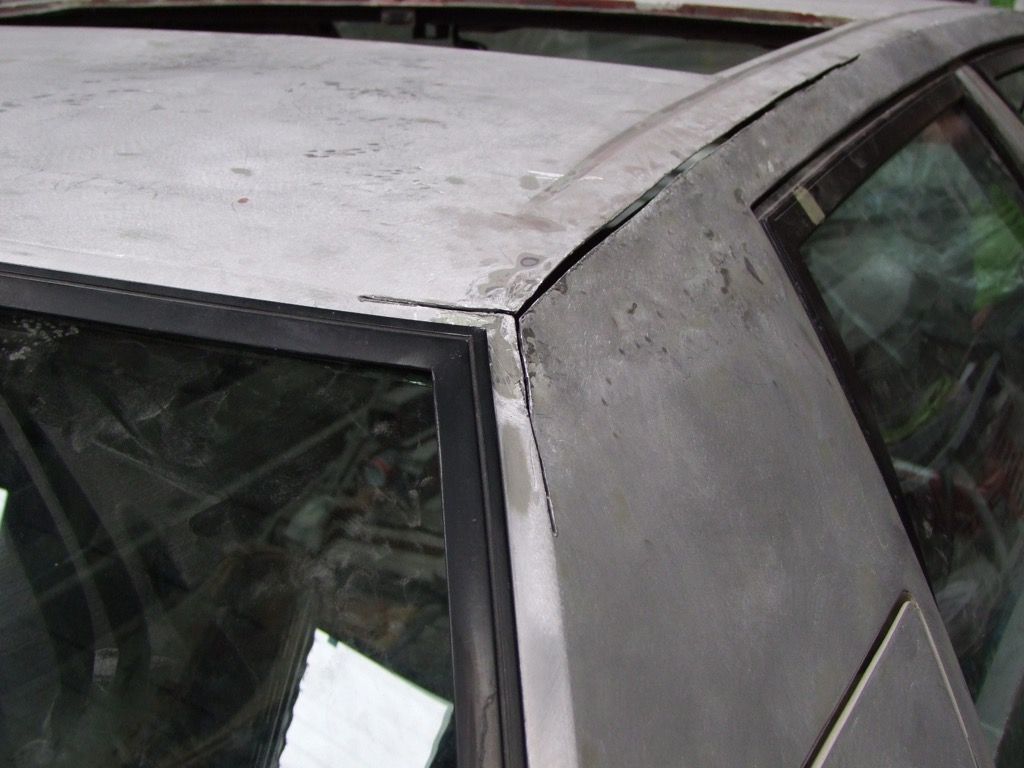
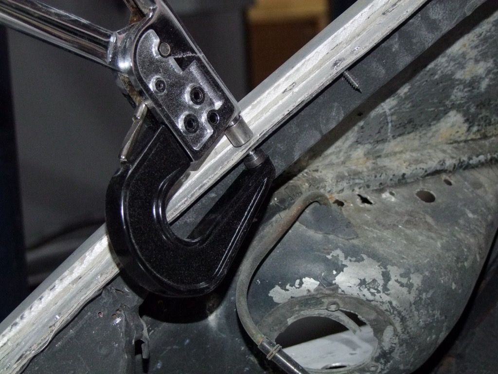
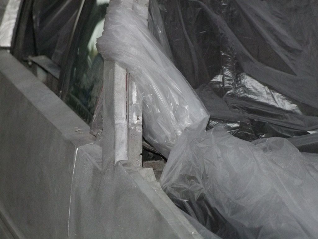
Now the body can have the canvas tape fitted in preparation for riveting the wing in place:
The rivets and tool are special ones. Self-tappers have been used to hold it in place in the meantime.
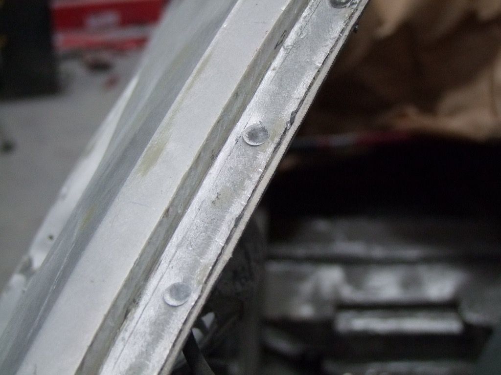
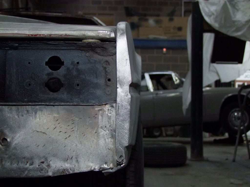
And now the welding can be done.
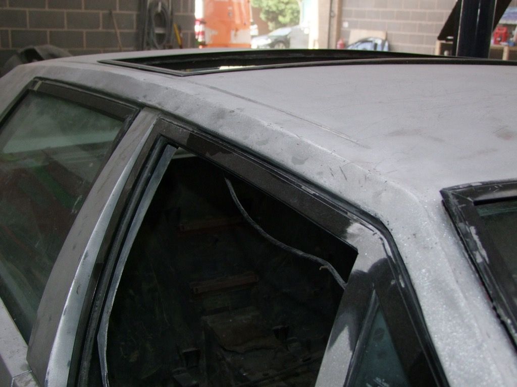
You can also see here that the door frames have been repaired. They have a groove to match the window surrounds on the earliest cars so there are no replacements. |
|
| Back to top |
|
|
Lagondanet
Administrator

Joined: 03 Jan 2007
Posts: 3108
Location: UK
|
| Posted: Thu Dec 17, 2015 9:39 am Post subject: |
|
|
Fantastic work!  |
|
| Back to top |
|
|
jonc
Joined: 21 Sep 2010
Posts: 584
Location: Cheshire, UK
|
| Posted: Sun Dec 20, 2015 10:03 am Post subject: |
|
|
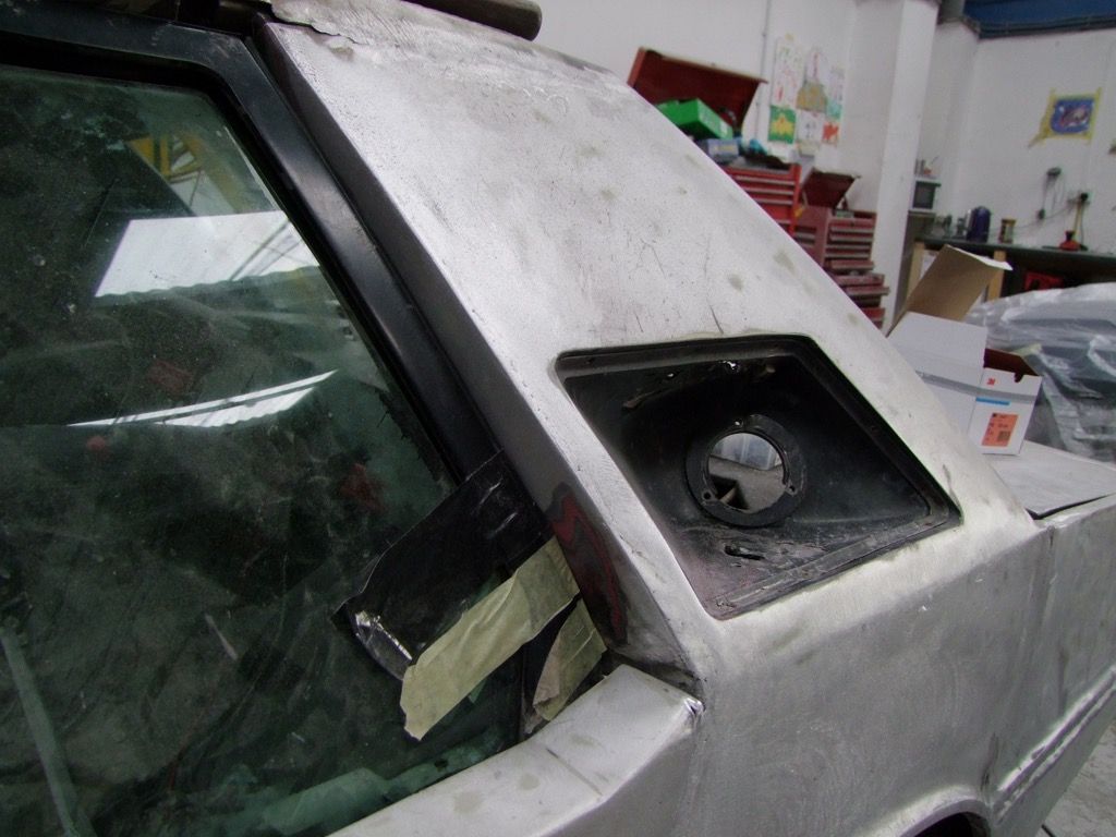
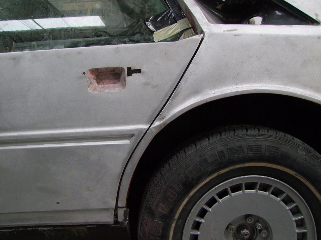
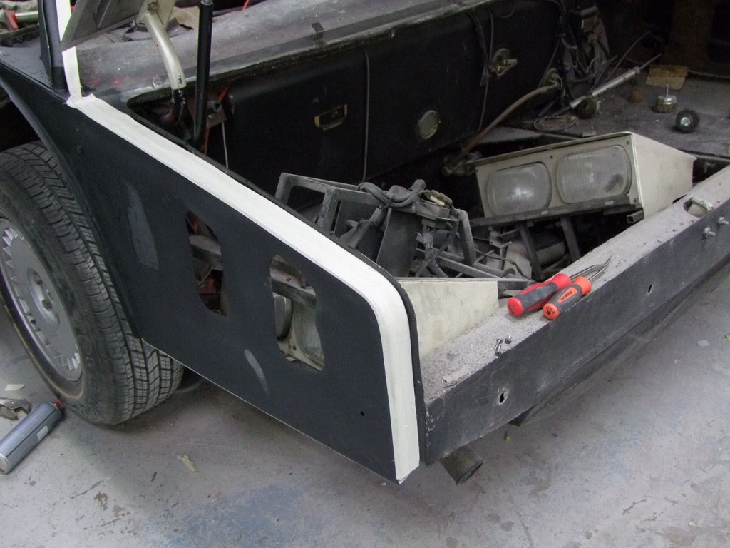
More small fiddly bits to repair now.
Another wing to refix.
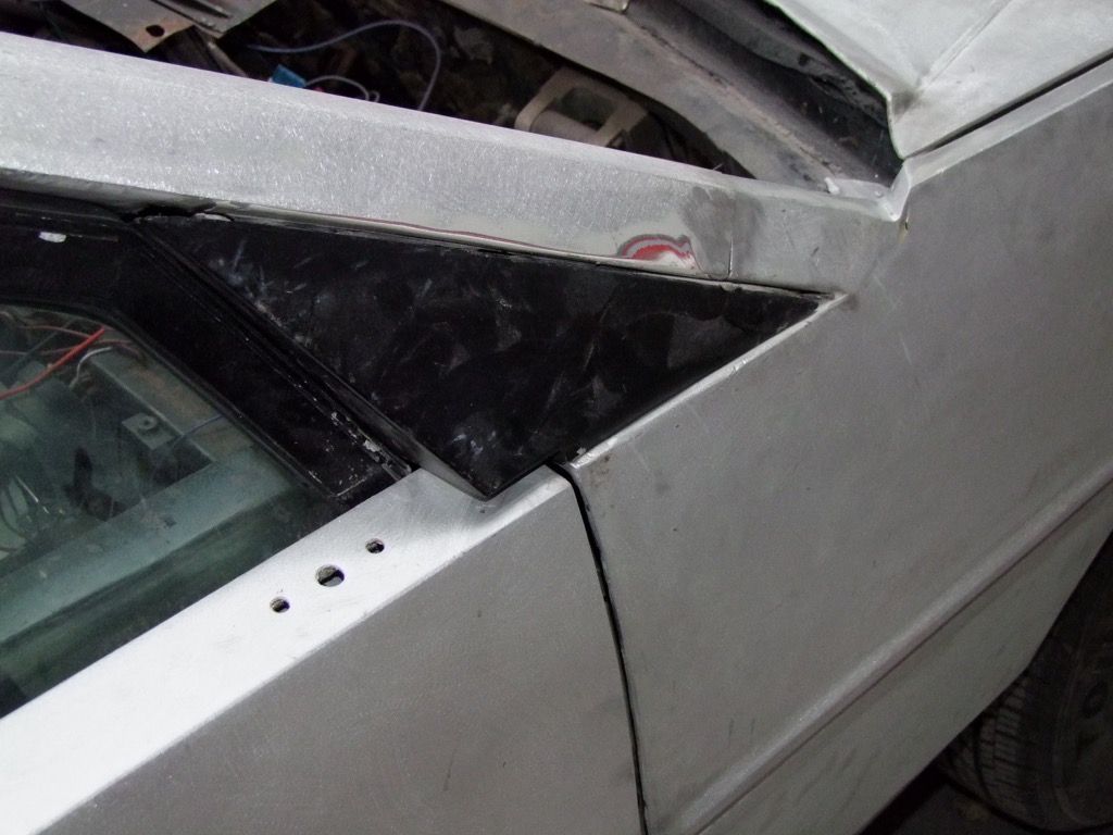
Those mirror holes in the top of the door are going as we are moving the mirror back to the A post.
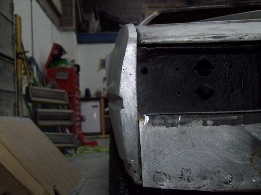
One other job to do at this stage. No matter how many times I have told garages not to close the boot lid by pressing on the top rear edge, they still did. This has the potential to cause denting and ripples, and also crack the paint across the back edge. I have seen it on many cars and had been thinking about a solution. Here it is:
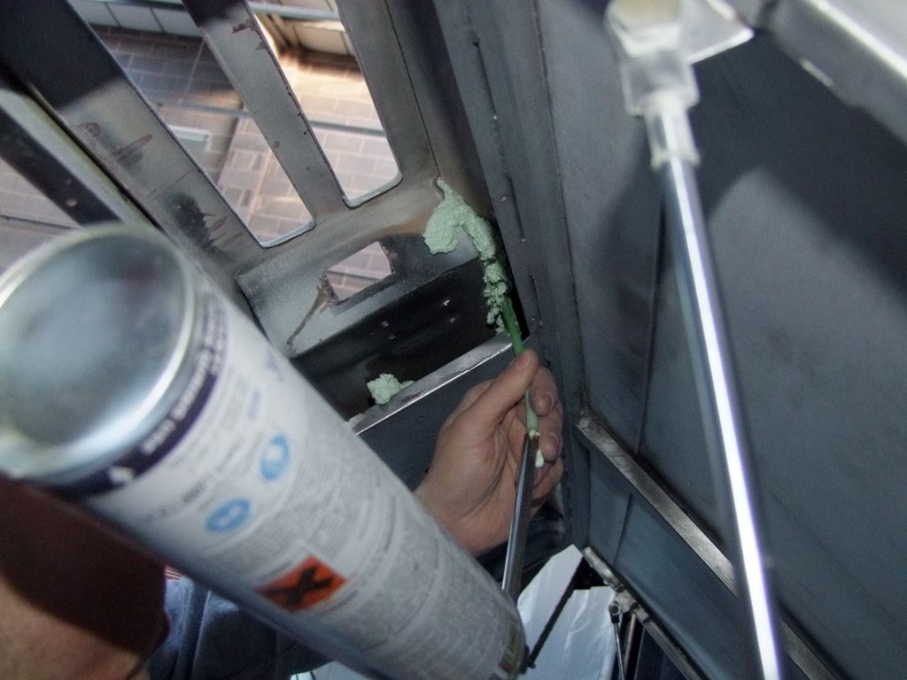
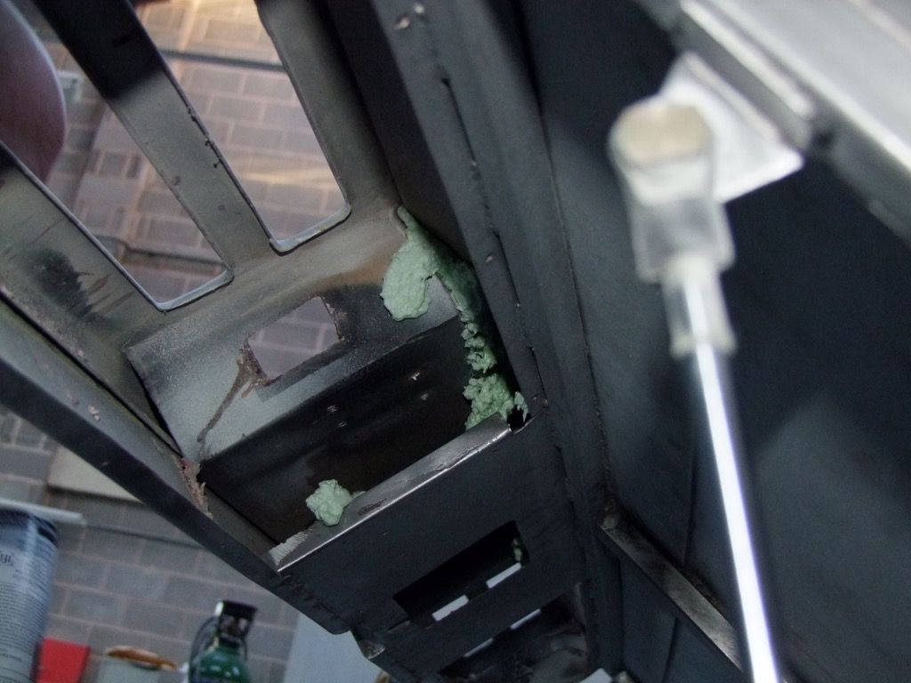
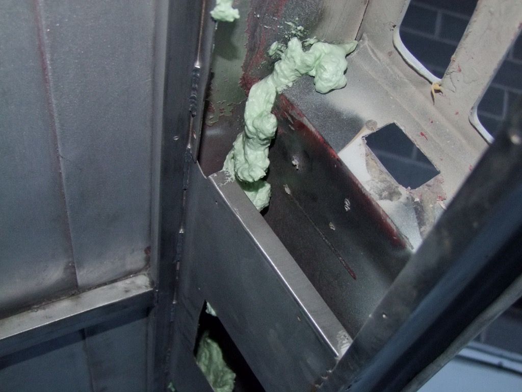
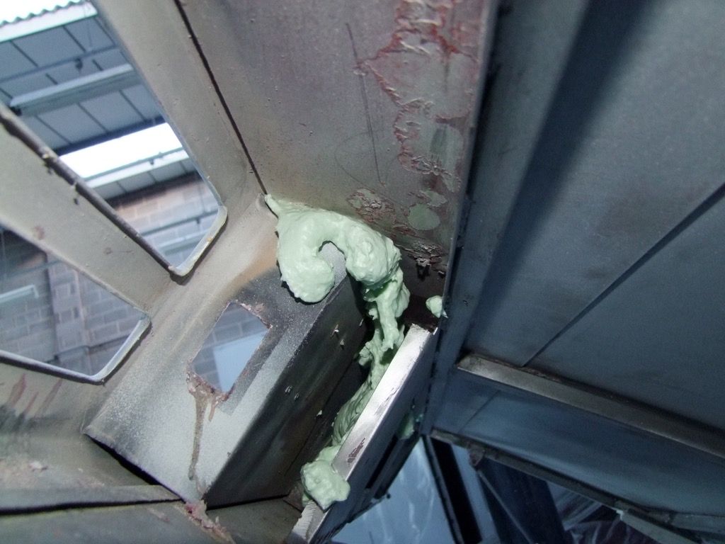
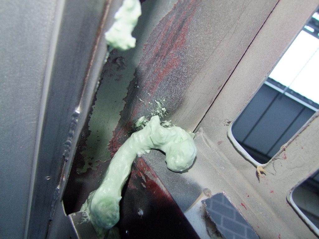
It needs to be trimmed after it has set properly, but this expanding foam filler will hopefully provide the support to limit any future damage to the lid. |
|
| Back to top |
|
|
jonc
Joined: 21 Sep 2010
Posts: 584
Location: Cheshire, UK
|
| Posted: Mon Dec 21, 2015 12:40 pm Post subject: |
|
|
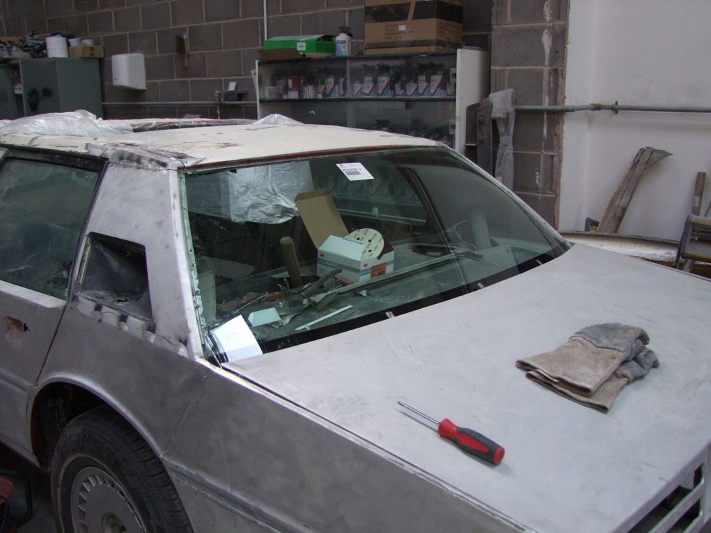
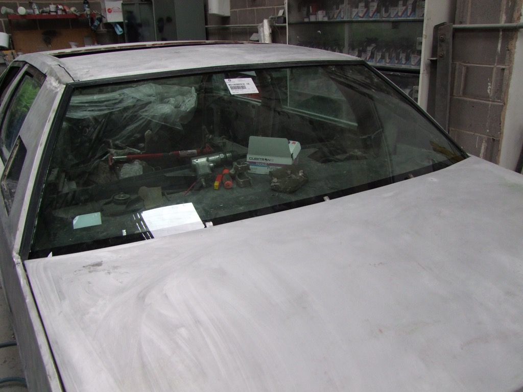
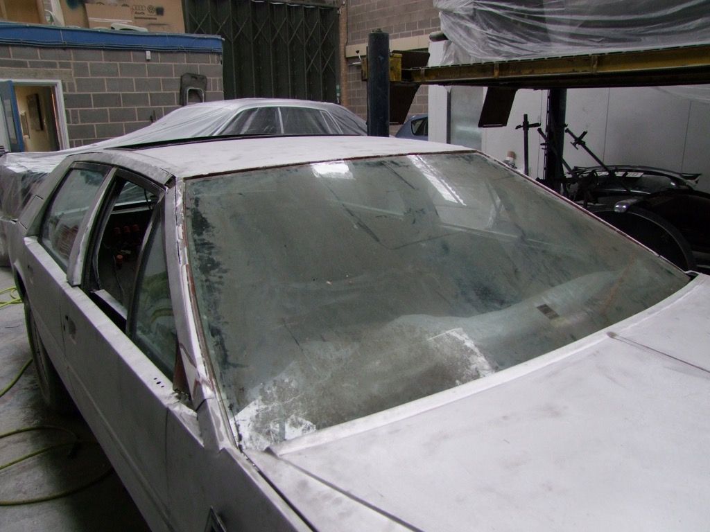
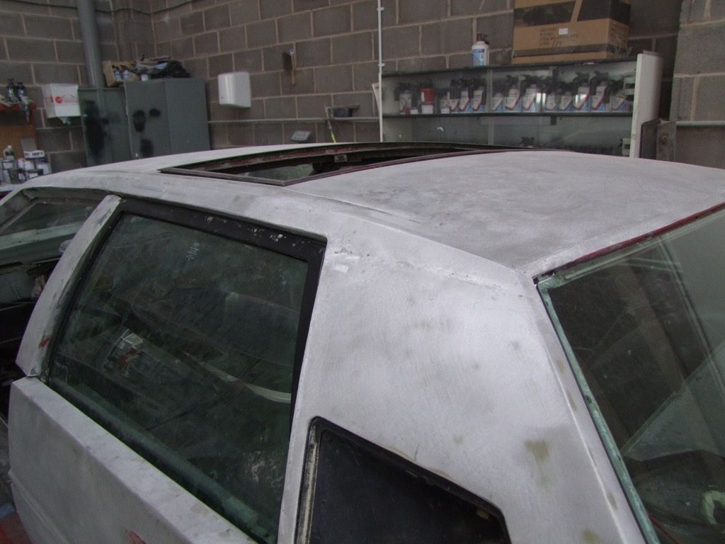
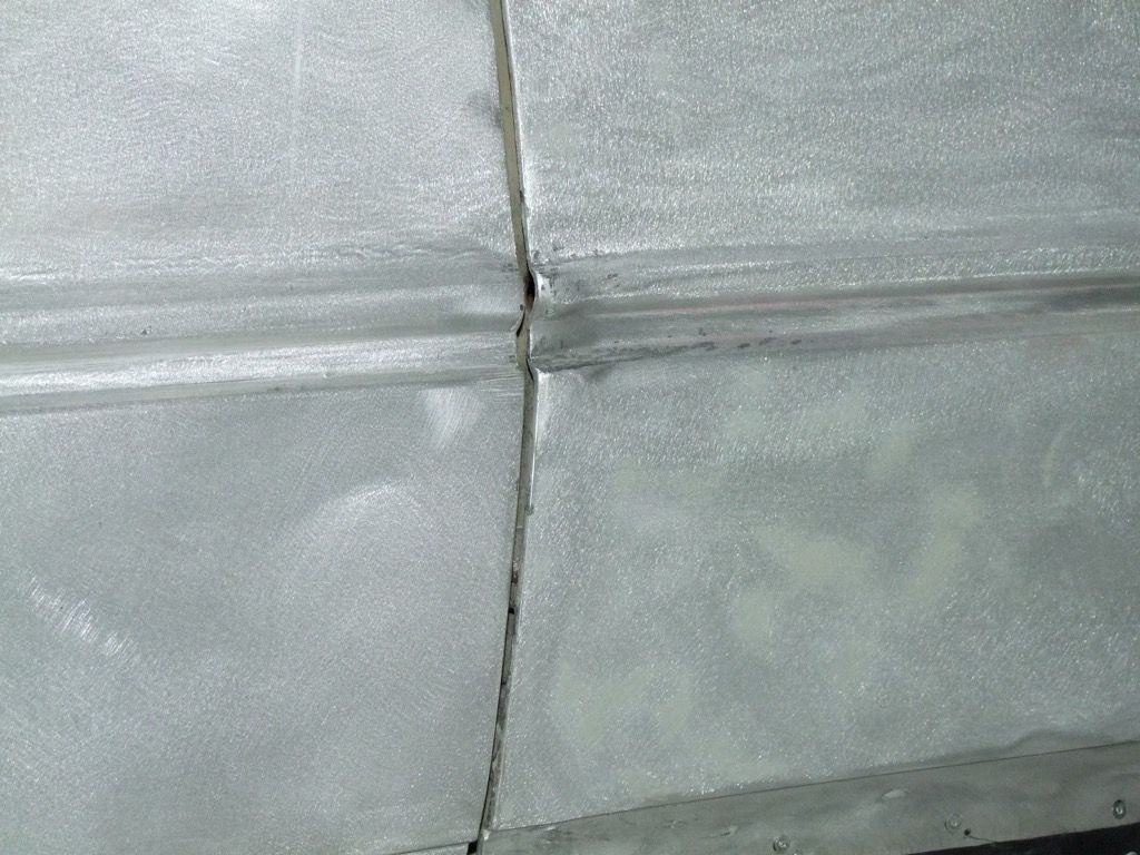
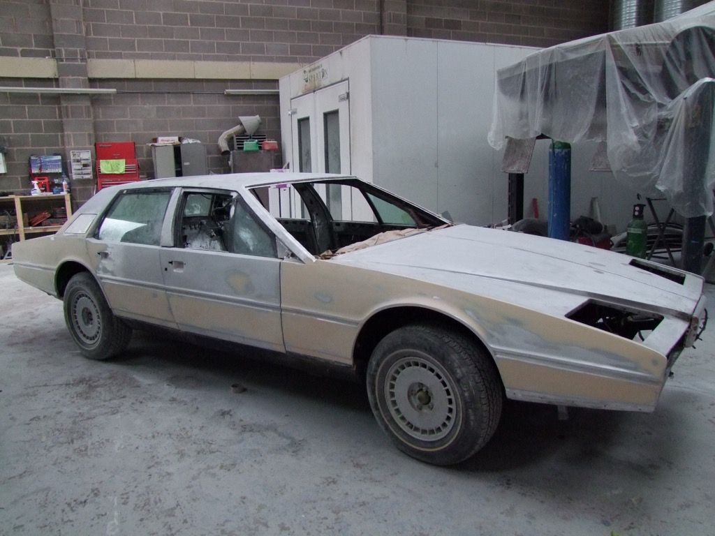
And so the next stage can begin. The body is receiving a very thin skim of body filler which is then flatted down to an extremely thin see-through layer.
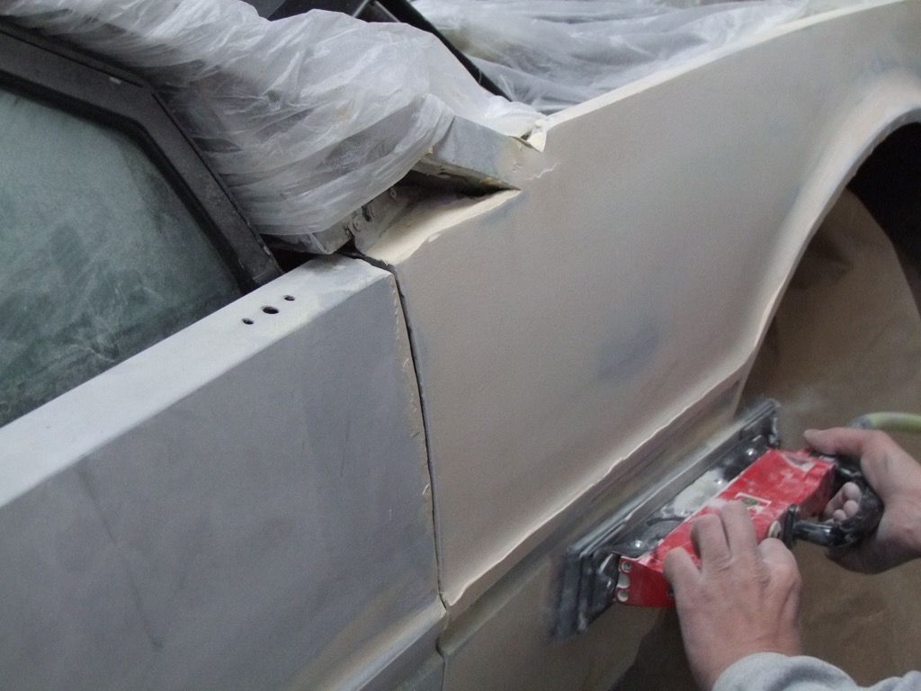
Oh, and the old mirror holes have been welded up.
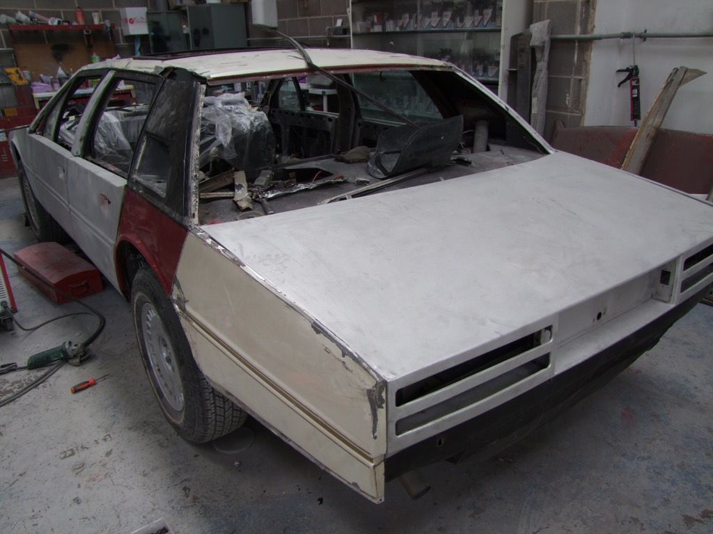
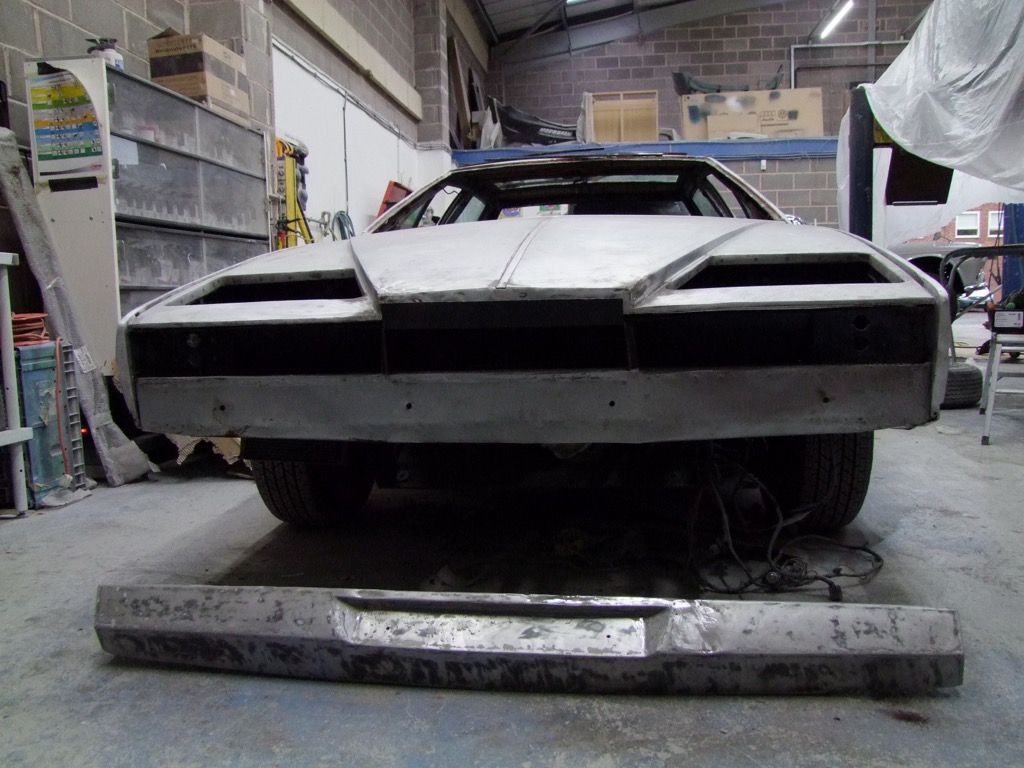
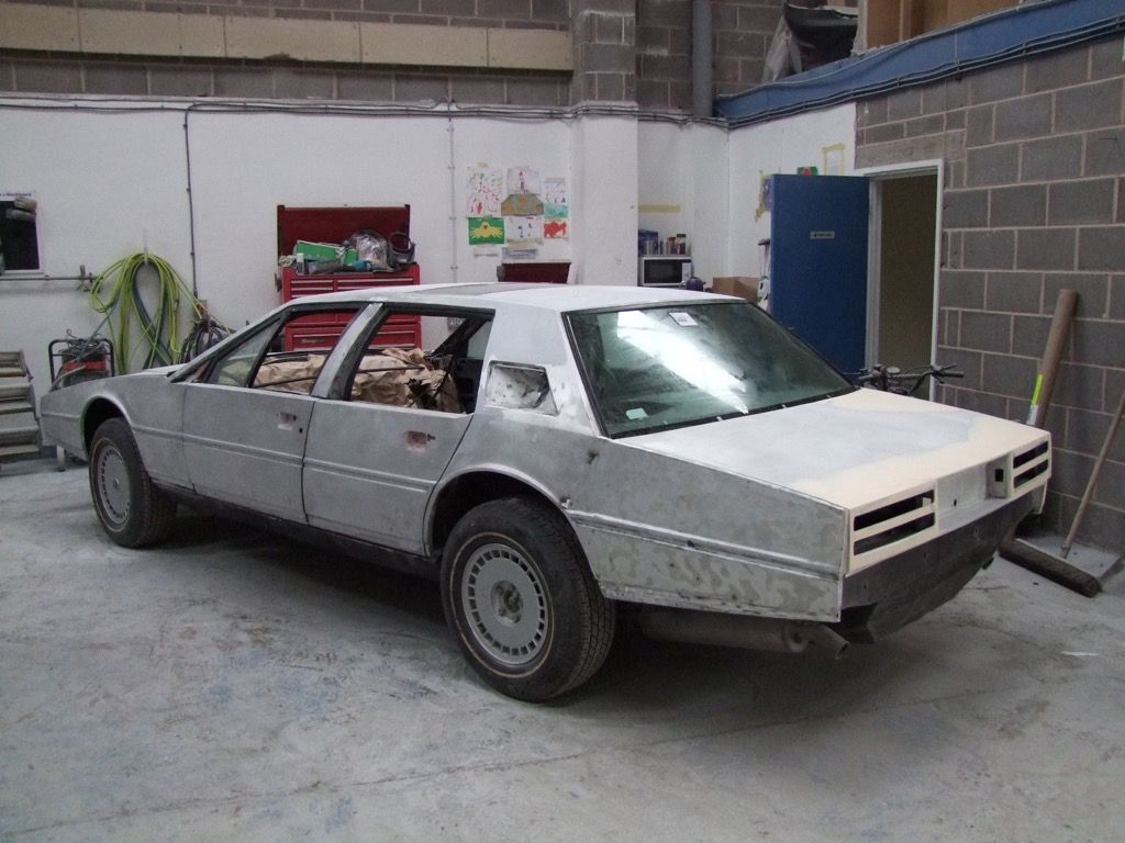
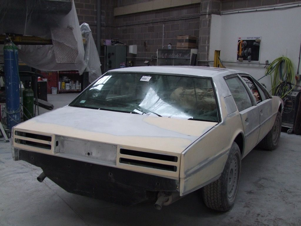
Lets just take a step back and see how far we have come:
 |
|
| Back to top |
|
|
Lagondanet
Administrator
Joined: 03 Jan 2007
Posts: 3108
Location: UK
|
| Posted: Mon Dec 21, 2015 7:13 pm Post subject: |
|
|
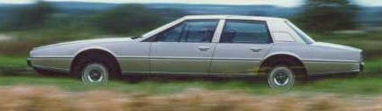
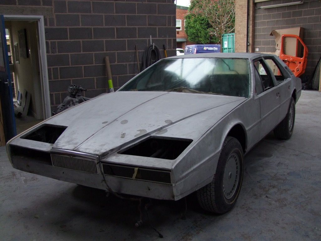
From this in 6 months!
 |
|
| Back to top |
|
|
jonc
Joined: 21 Sep 2010
Posts: 584
Location: Cheshire, UK
|
| Posted: Wed Dec 23, 2015 11:37 am Post subject: |
|
|
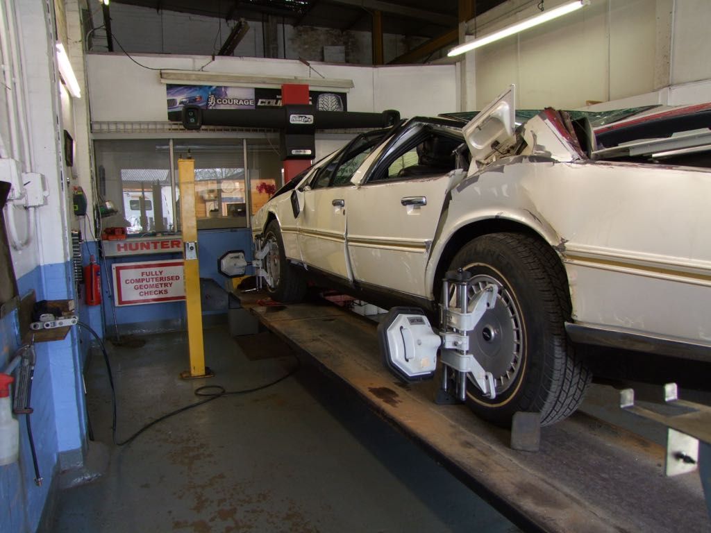
Indeed. And with all the steelwork corrosion sorted as well.
On to something else. While the bodywork is with David, I have been dealing with the dash. As I said earlier, the LED instrument panel was converted to analogue in the late 1990s. The owner didn't really want this change, but was persuaded by WS who said it would be more reliable, and in any case they didn't have a suitable replacement LED instrument panel.
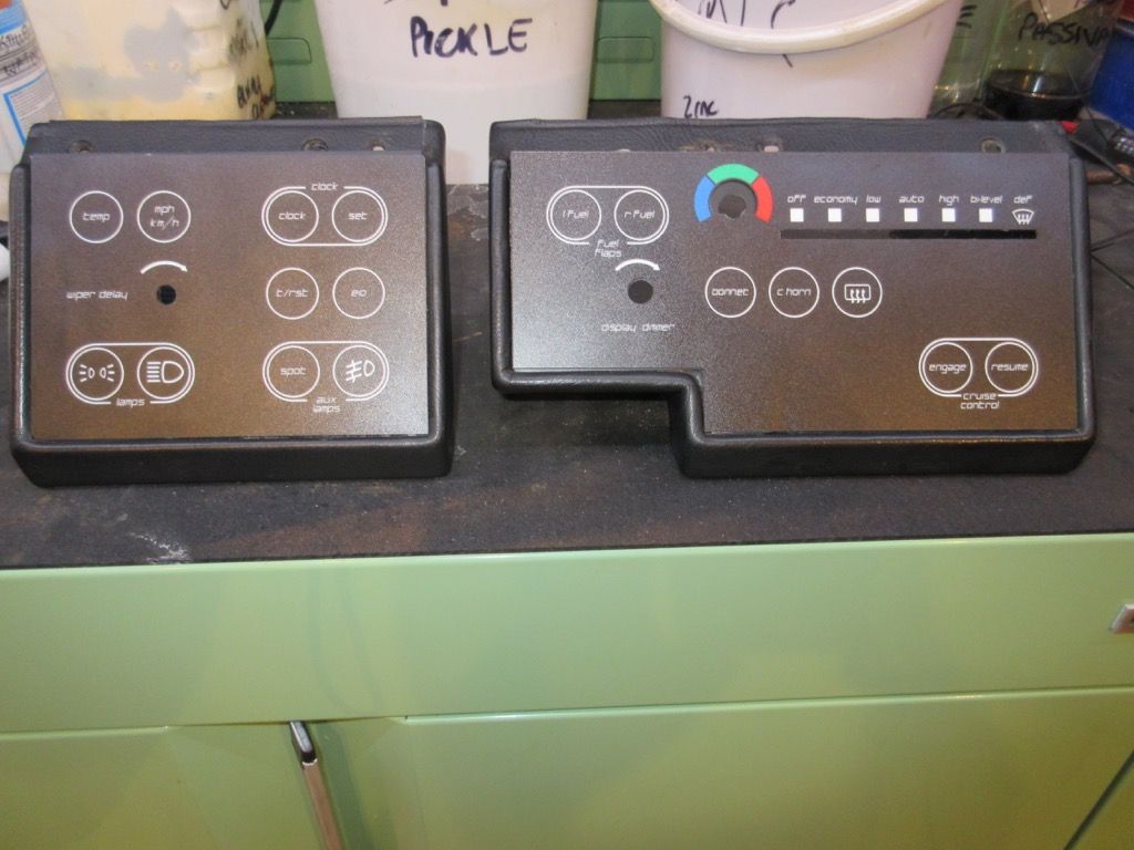
The car also has the mechanical push-buttons instead of touch switches, and conversion to a simple heater system (also done by WS in the late '90s):
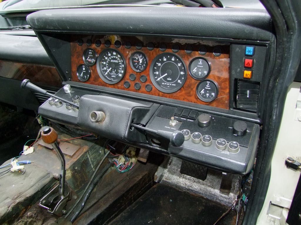
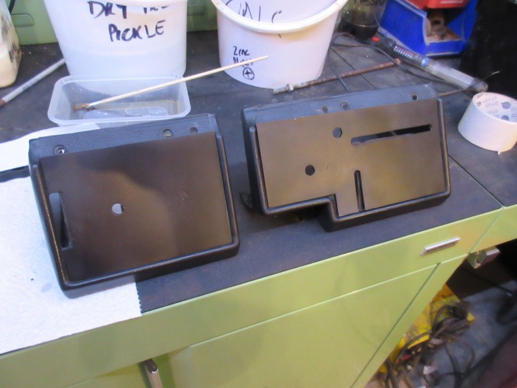
First the binnacles. With the controls removed, I am left with this:
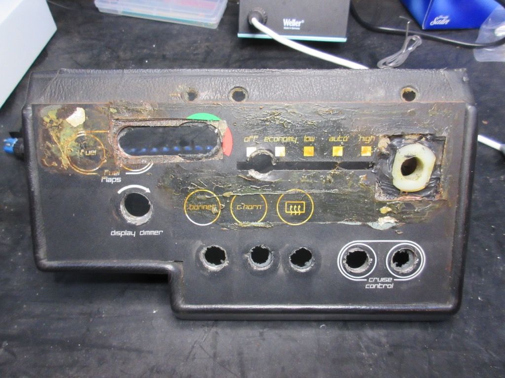
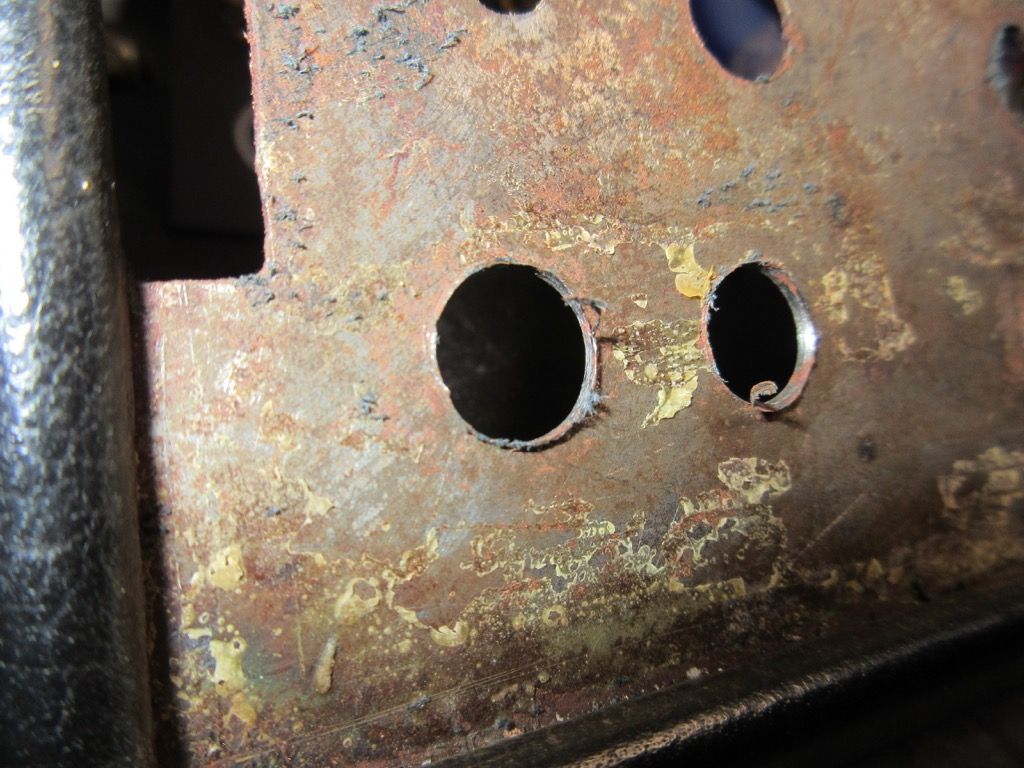
The insides have never been painted. Also, the push-buttons had their holes drilled straight through the old touch switches which has left some untidy holes.
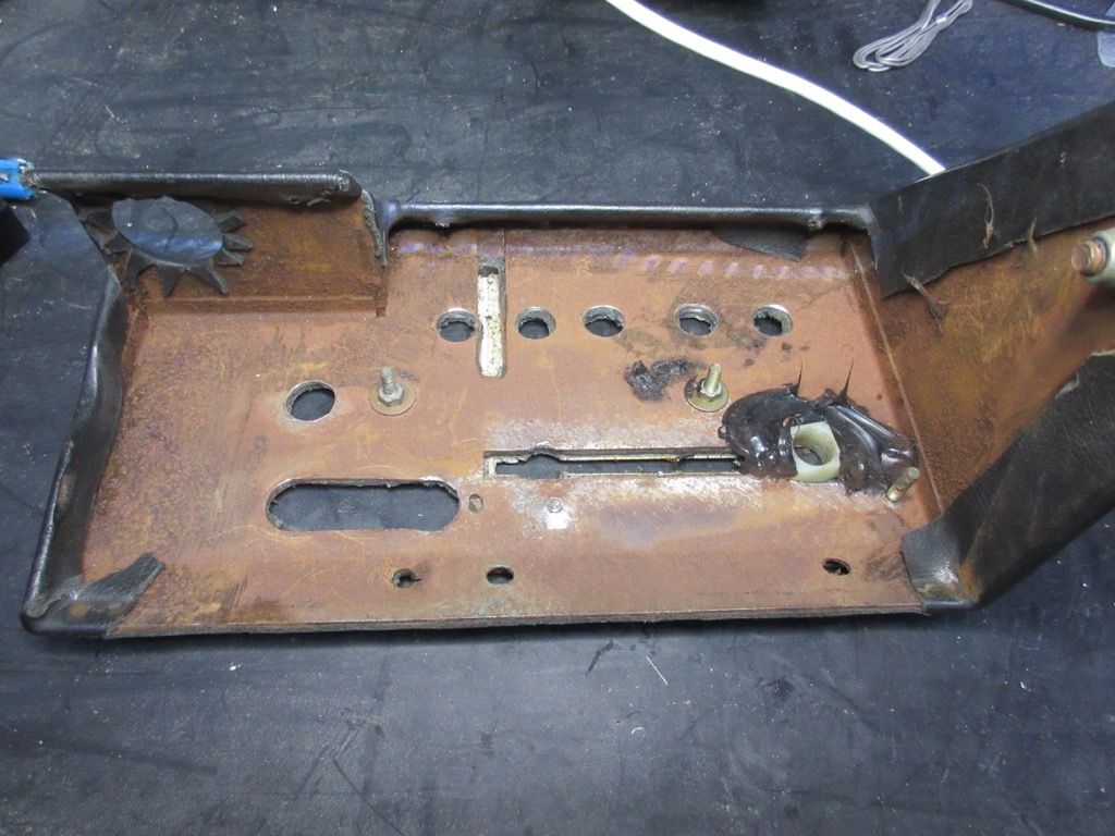
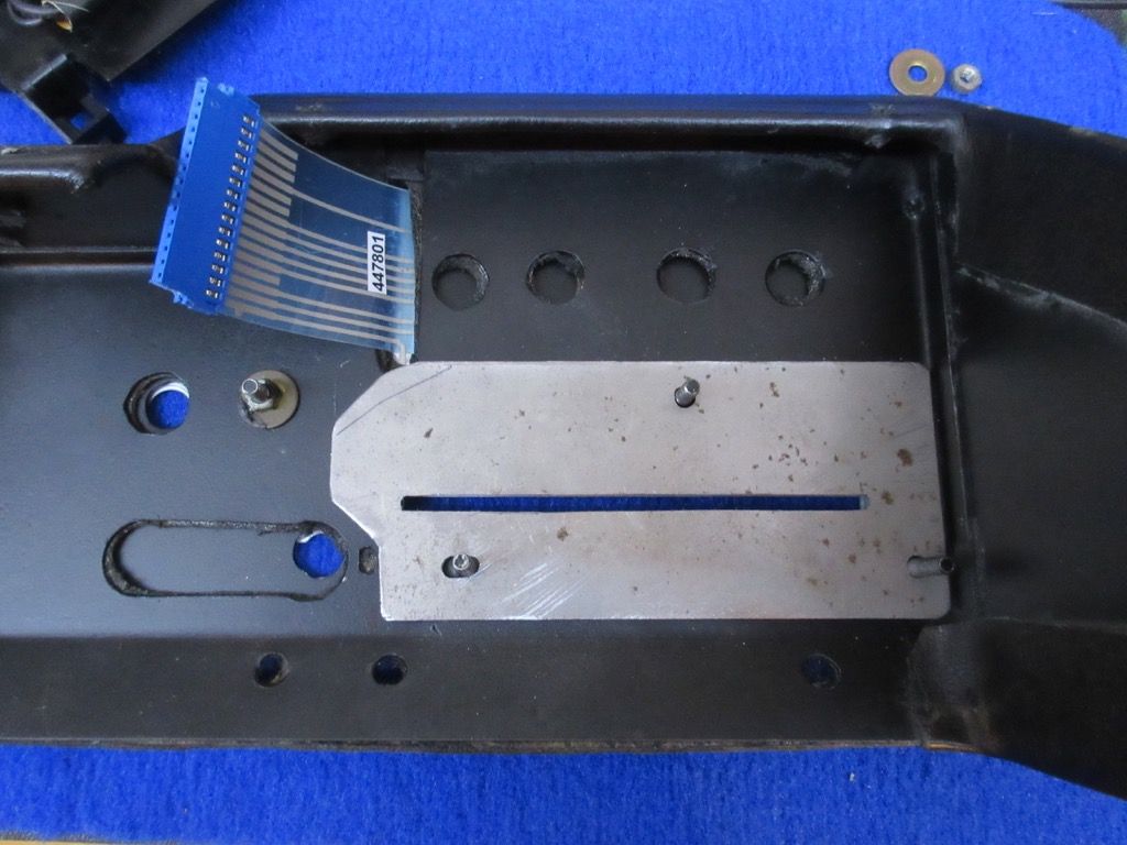
The old touch membranes with their steel backing plate are removed and the inside of the binnacles cleaned up for painting.
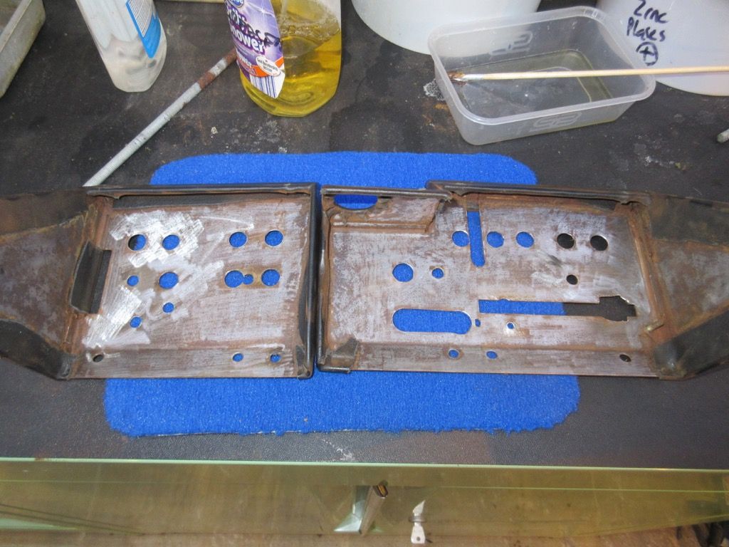
The touch membrane backing plates can't be reused though because of the additional holes. They won't give the support needed for the membranes - most of the holes are below where you will need to press. I am making some new ones.
In case anyone needs to do this in future, here are my measurements:
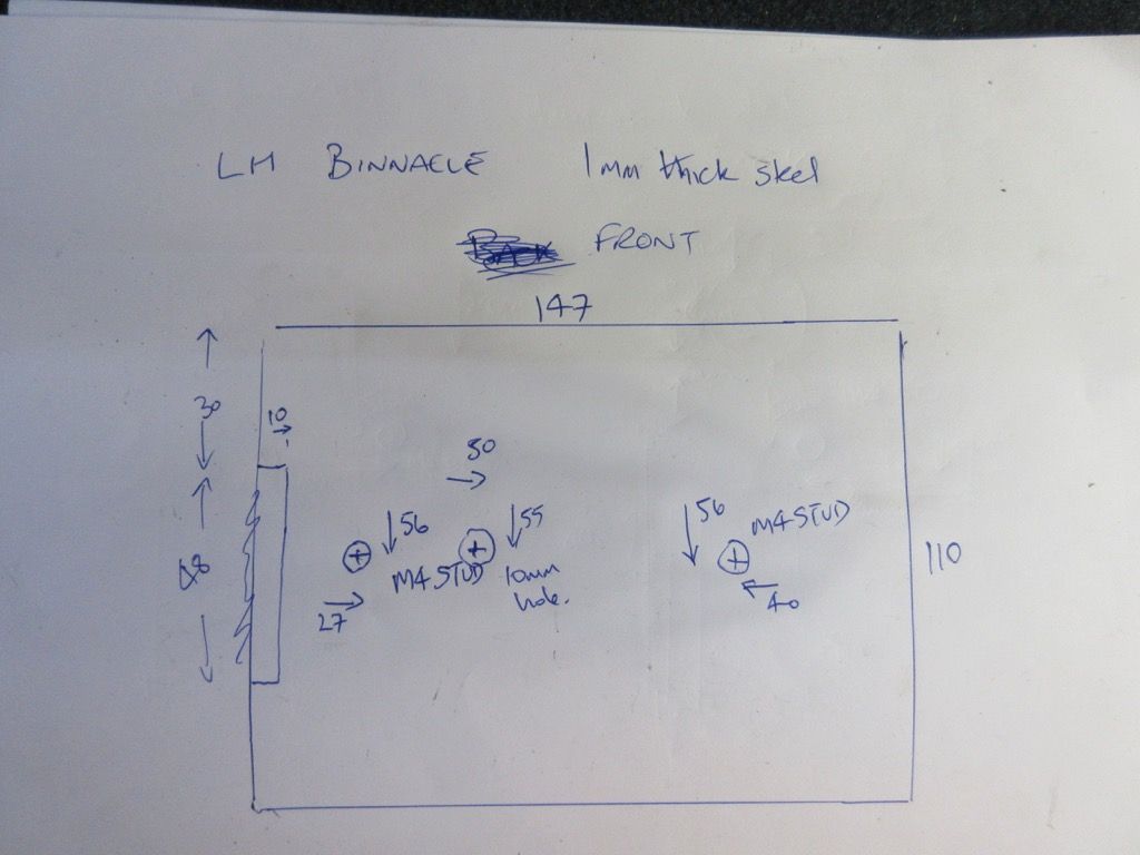
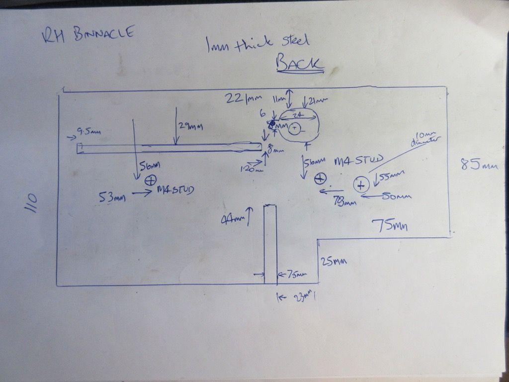
These are slightly different to standard because I am not fitting the Cadillac temperature control - I am going to use a standard fitting potentiometer which has a nut to hold it in place.
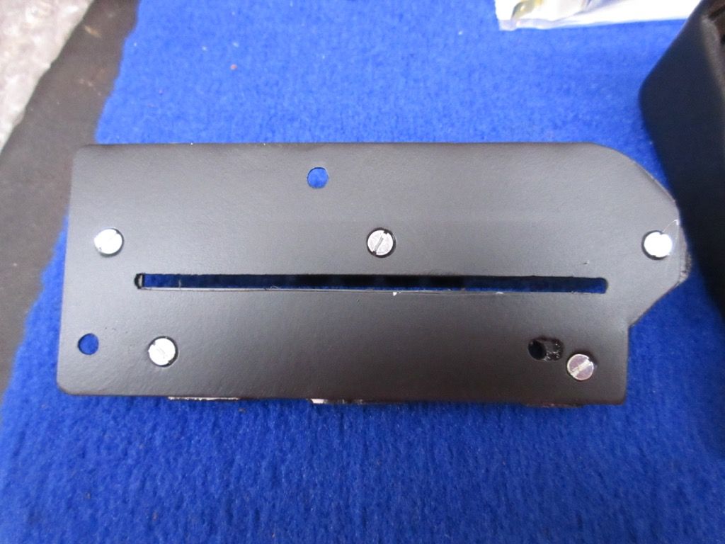
The plates are held in place by two M4 studs which I have welded in place and ground flat.
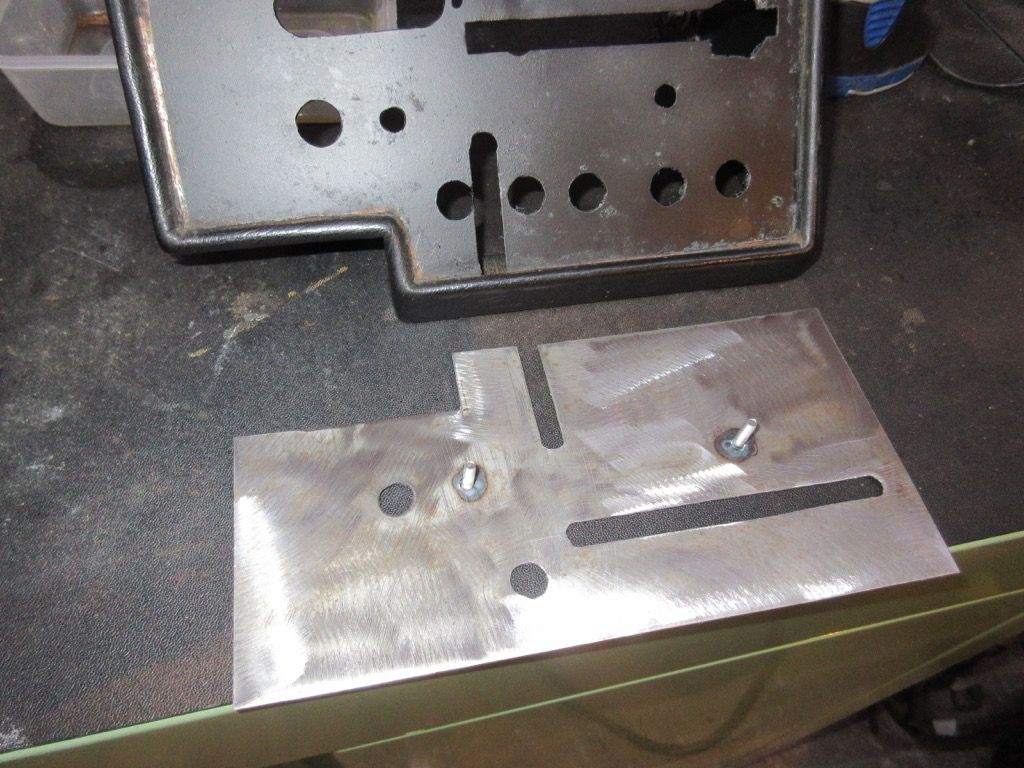
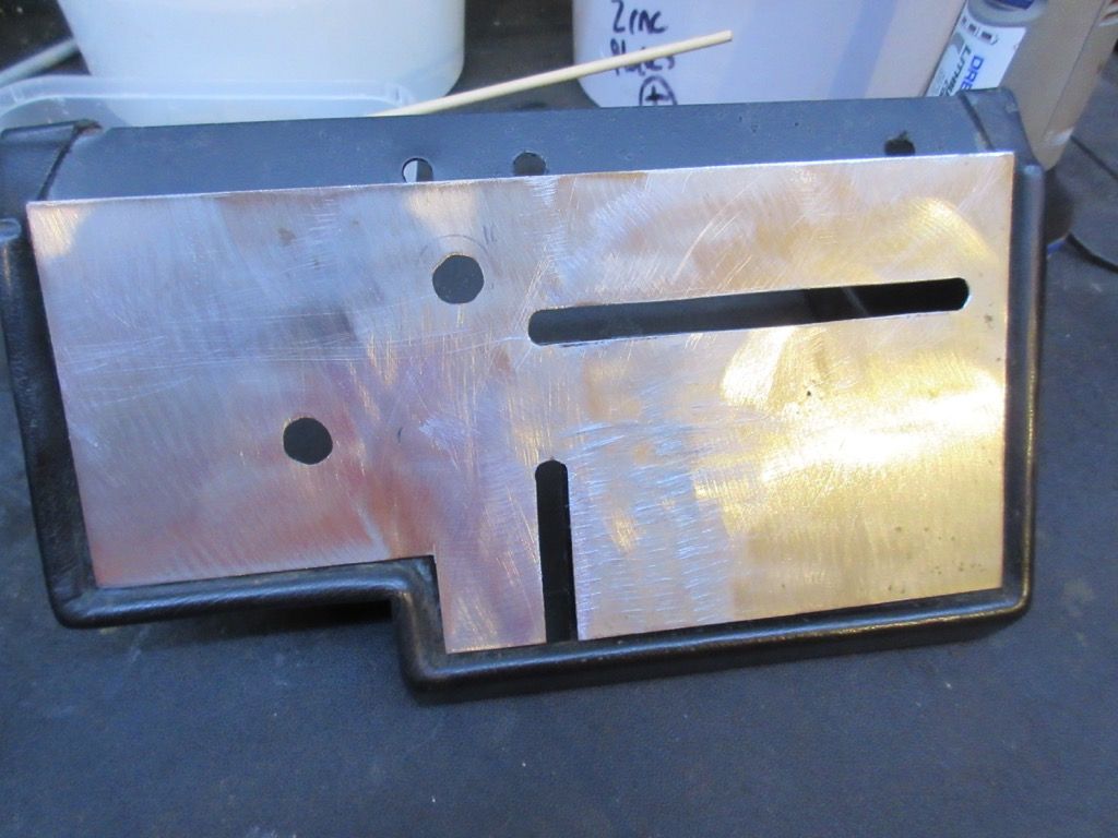
And painted:
The touch membranes are then stuck onto them - they have a self-adhesive backing and you only get one go at doing it right!
 |
|
| Back to top |
|
|
jonc
Joined: 21 Sep 2010
Posts: 584
Location: Cheshire, UK
|
| Posted: Wed Dec 23, 2015 11:52 am Post subject: |
|
|
Now the heater control. I have found a new-old-stock one from the USA and I am doing the same job on the mounting bracket as I did on 277.
This is because the plastic of the control once you have cut it to fit is not very strong.
I have also made a mounting bracket for the demist microswitch:
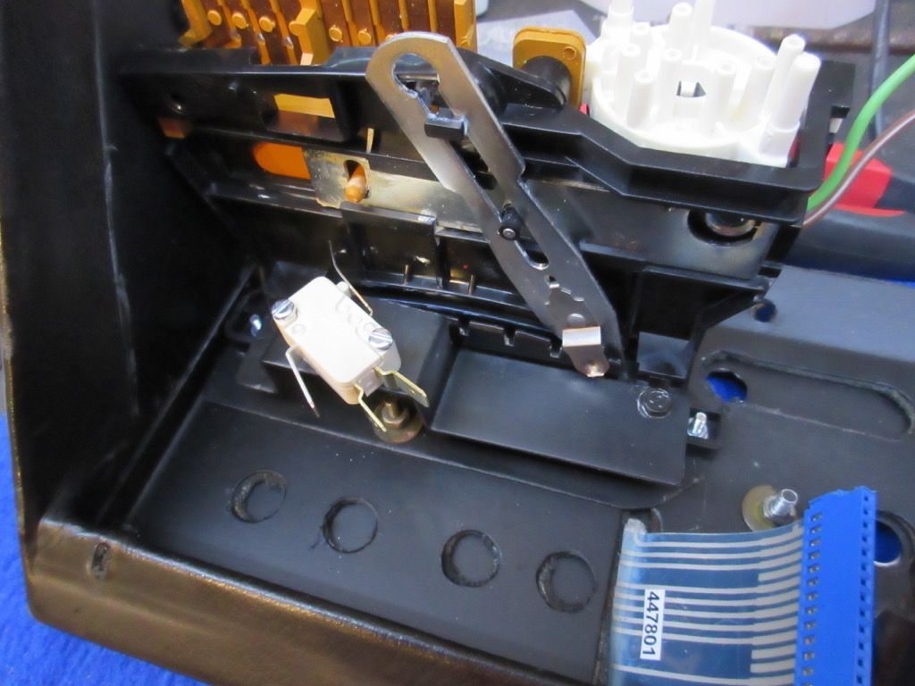
Here is the replacement temperature control in place:
Since I couldn't find a binnacle interface, I have made one. That is already documented here: http://lagondanet.com/bb/viewtopic.php?t=1204
And here it is:
The touch membranes connect to this, and then the interface must connect to where the push-switches did. I have reverse-engineered the wiring so I know what pin on their connectors does what. This means I can make a conversion loom which should plug straight in and work.
This is the end which connects to the binnacle interface:
And the loom for binnacle interface to car loom:
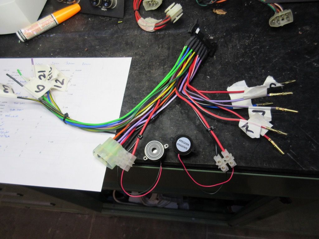
I have also added the buzzers. The left side of the loom goes to the LED instrument panel for things like clock reset etc.
Fortunately, David has been able to help me out with an LED instrument panel - one which will go perfectly with this car.. |
|
| Back to top |
|
|
Lagondanet
Administrator
Joined: 03 Jan 2007
Posts: 3108
Location: UK
|
| Posted: Wed Dec 23, 2015 12:21 pm Post subject: |
|
|
| You have been busy! |
|
| Back to top |
|
|
jonc
Joined: 21 Sep 2010
Posts: 584
Location: Cheshire, UK
|
| Posted: Wed Dec 23, 2015 5:04 pm Post subject: |
|
|
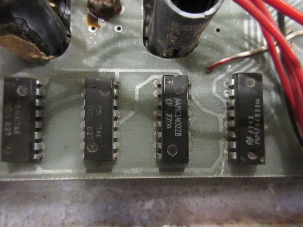
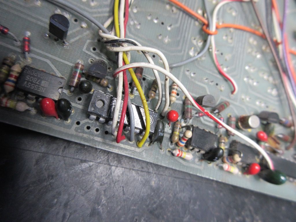
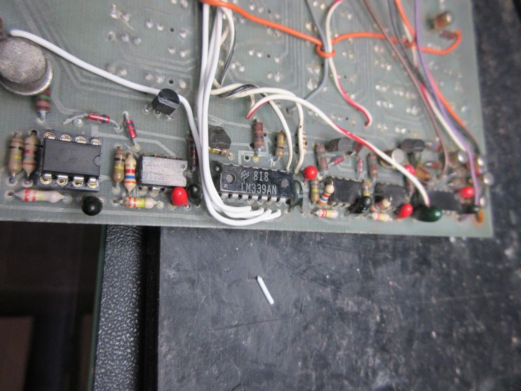
David has sourced an instrument panel for me. It is a prototype which pre-dates the early 'wavy line' layout.
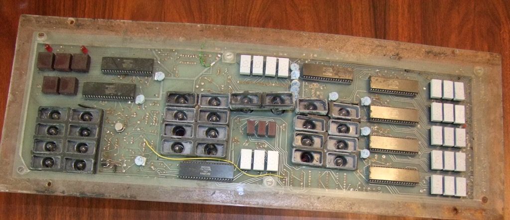
I can tell it is a prototype because the basic layout of the components matches the early production one, but there are a number of components which have been added after the circuit design was committed to make the circuit board. I can see these same components on the production panel from 13277, but incorporated into the circuit layout. It also has different connectors.
The layout 'artwork' is also pretty scrappy - maybe done in a hurry?
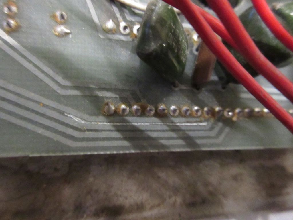
Also, there are many more of the chips soldered directly to the board (which I don't thank them for - it will make replacement much slower).
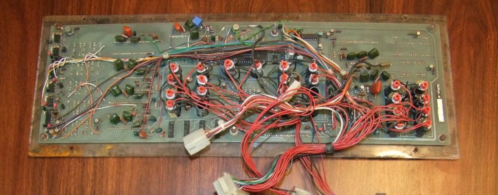
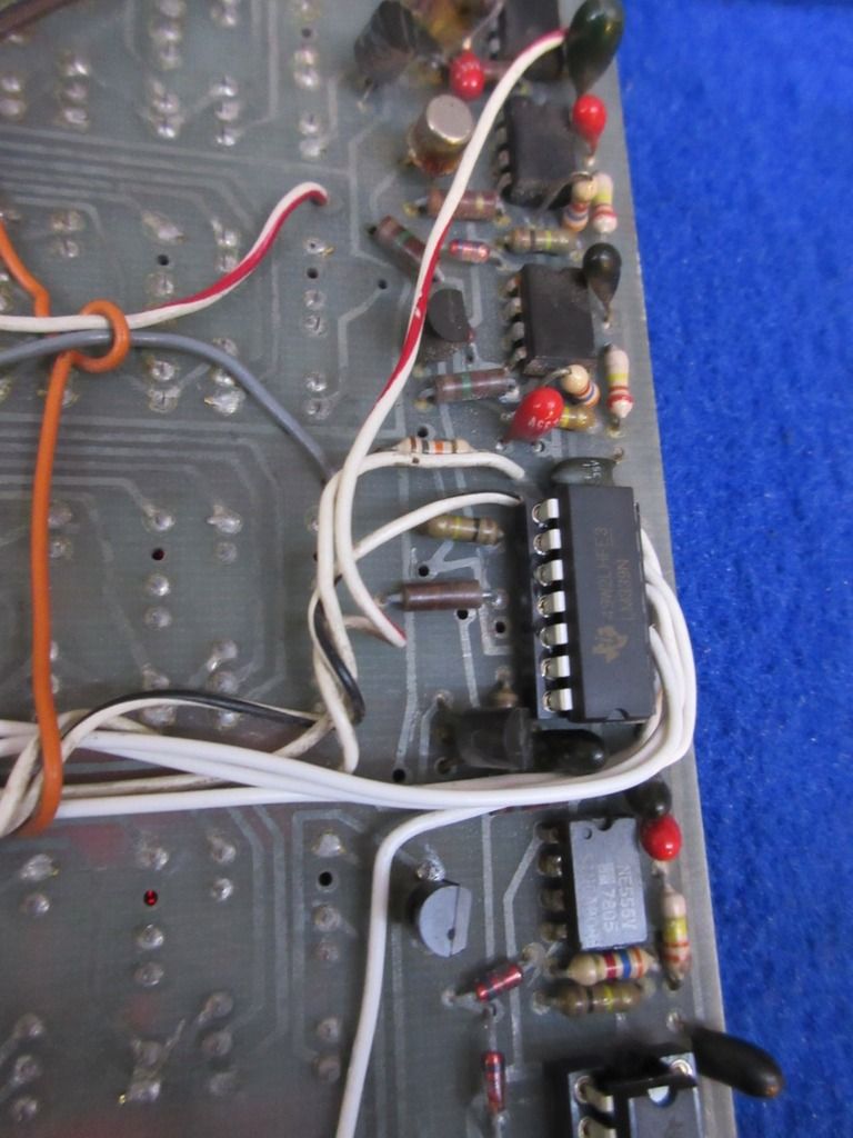
Here is the same area on a production board for comparison:
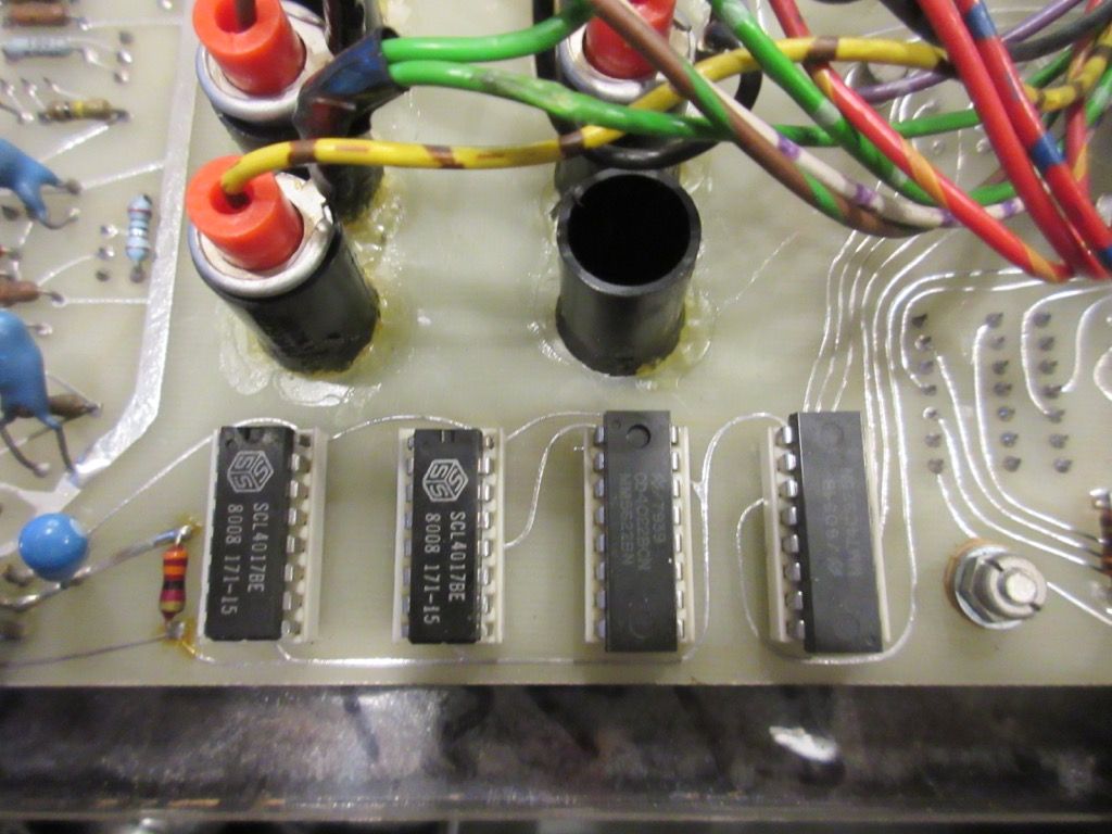
It is for the trip counter in case you are interested. You can see the chips are in sockets for easy replacement, but also the tracks of the circuit board are much finer and neater. The prototype artwork has been laid out using Letraset-type transfers but is not neat, and I can see they moved to free-form because the wider tracks on the prototype meant they couldn't get all the wiring they needed to travel around the board. The proper solution to this is to make your artwork double-sized and then photo-reduce it for production, which gives you finer tracks and a neater overall finish. I am pretty sure looking at the prototype that they did it 1:1 which is why they had the problem.
The best thing about my prototype board? It is serial number 4!
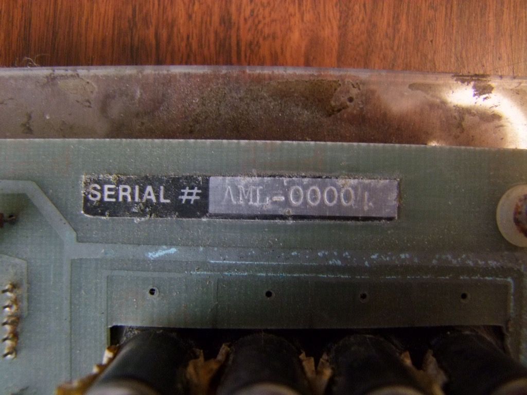
I wonder if any of it works? |
|
| Back to top |
|
|
jonc
Joined: 21 Sep 2010
Posts: 584
Location: Cheshire, UK
|
| Posted: Wed Dec 23, 2015 6:00 pm Post subject: |
|
|
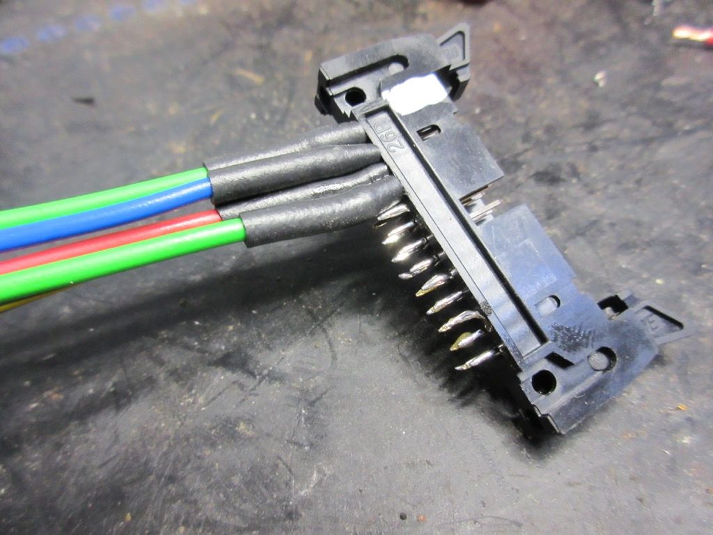
First things first - I have to work out how to connect it up. It has two connectors for the electronics:
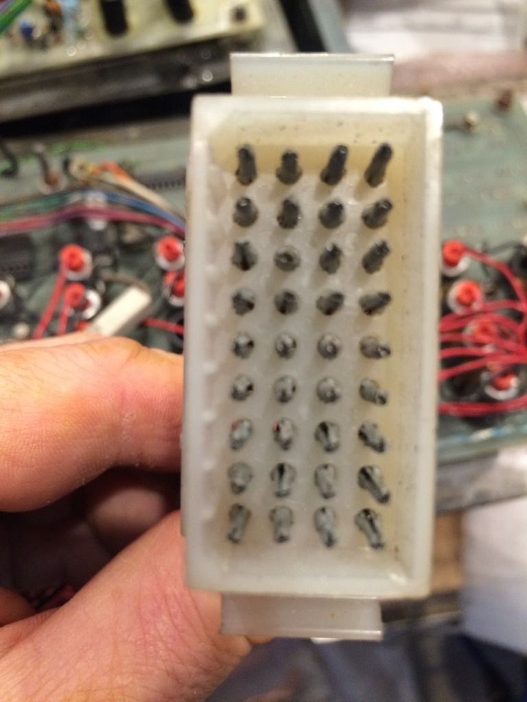
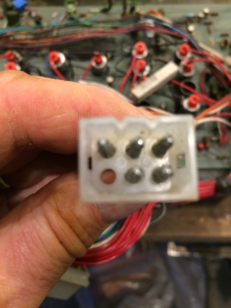
With a big of circuit tracing, I can tell the small one is a power supply connector and the bigger one is everything else. The big one connects to the car loom, and the small one just the power supply. This is different to production where the power supply is connected into the car loom, and there is then one multi-plug which sends the regulated power to the instrument panel along with all the sensors etc.
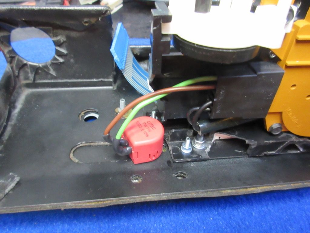
I have sourced a power supply:
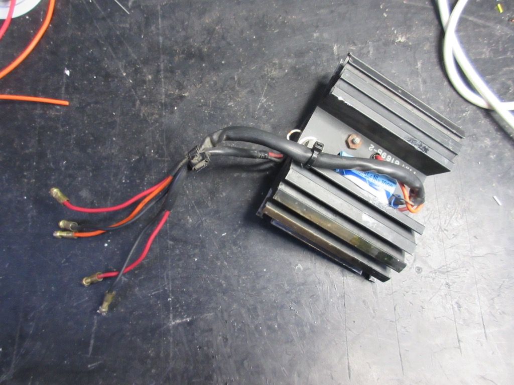
It is interesting to note that this has blue plastic-insulated crimps on it (barely visible on the picture in the middle of the heatsink). This is just like the display dimmer control I have on 277 (which I am measuring here):
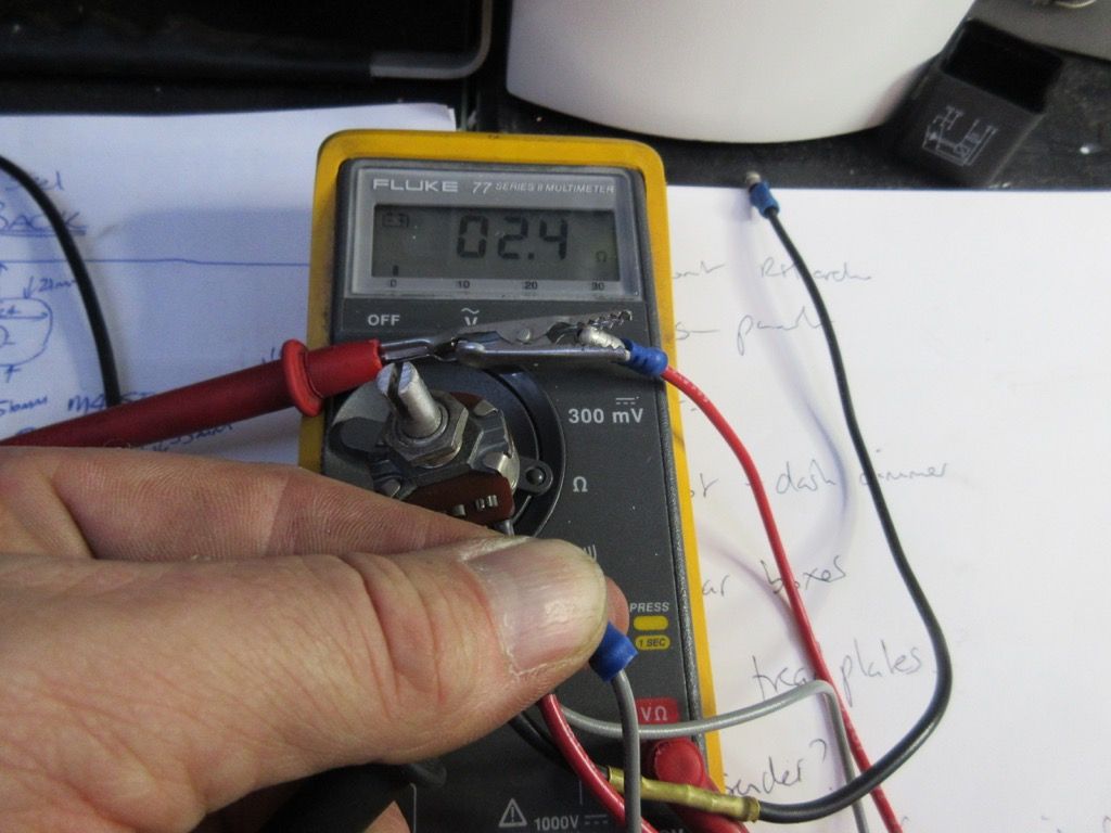
This says Javelina supplied AML with the instrument panel, the power supply and the display dimmer, which of course makes perfect sense..
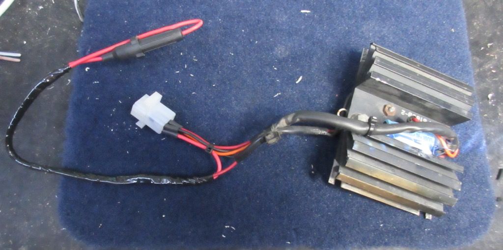
Now I have modified the loom of the power supply to incorporate the connector to mate with the instrument panel. I have also included an in-line fuseholder which is there to protect the power supply, instrument panel and binnacle interface. The fusebox fuse is 8A whereas this one is 2A.
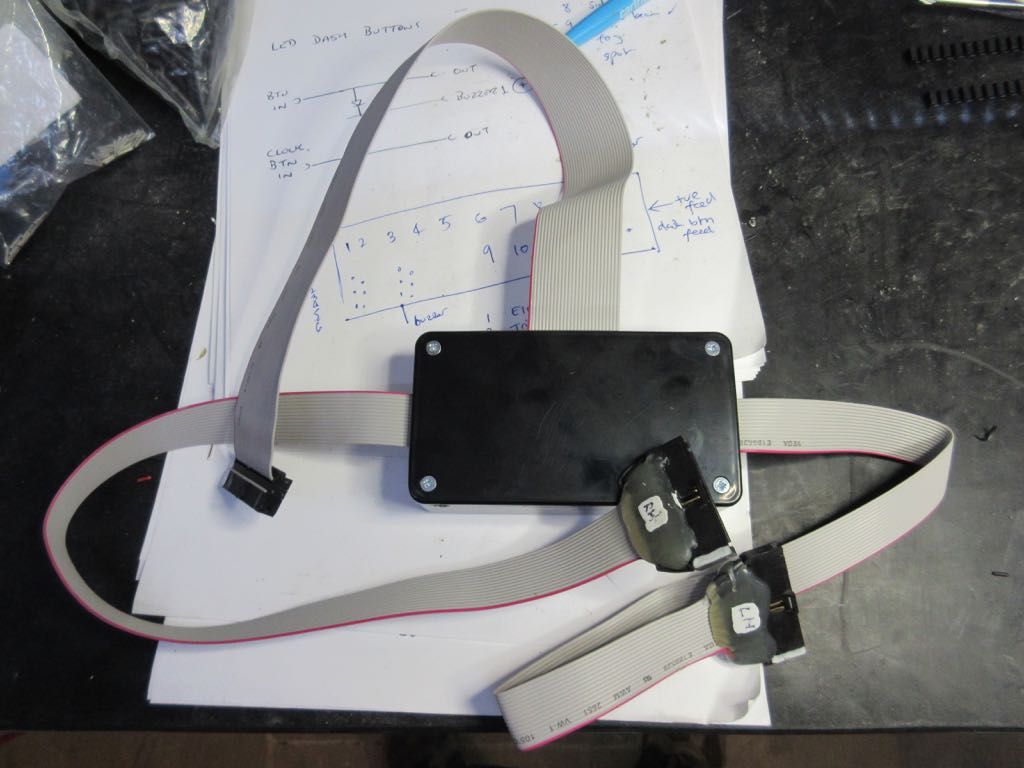
I also have a plan for how I am going to set up the instrument panel for testing. I have made a break-out-box. Well, actually I bought one and modified it. I found this on eBay:
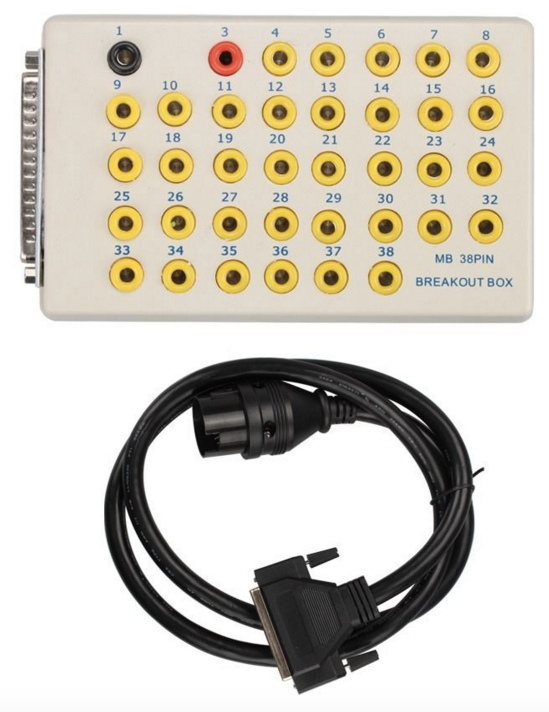
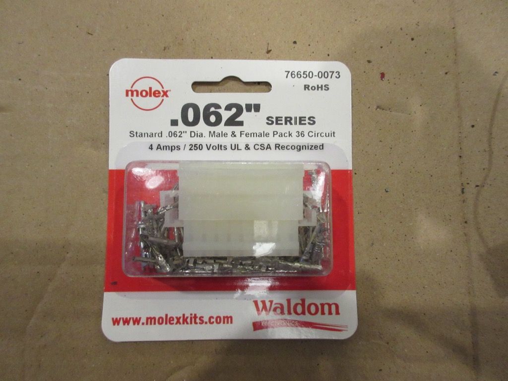
..which is for connecting to a Mercedes. It was shipped directly from Hong Kong and I couldn't have bought the parts to make it for what I paid. I have converted the end to the standard 26 pin connector used on the binnacle interface and standard instrument panel. Now I just need an end for this panel's connector, which turns out to be a 0.062 inch Molex and I have had to order it from the USA.
Here is my break-out loom:
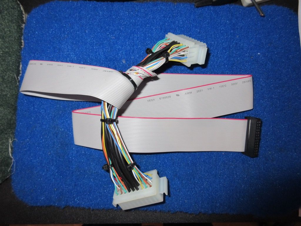
It has a male and female connector so it can be inserted in-line with the instruments in the car and give access to all the signals.
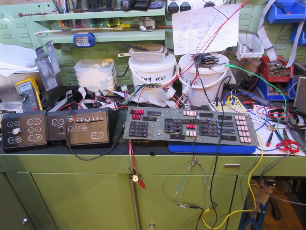
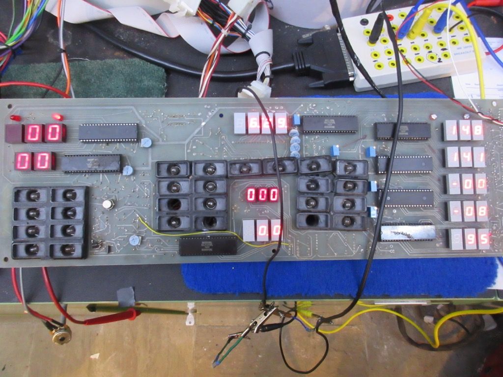
So now I can fire it up.
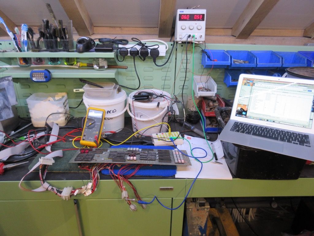
And some of it actually works:
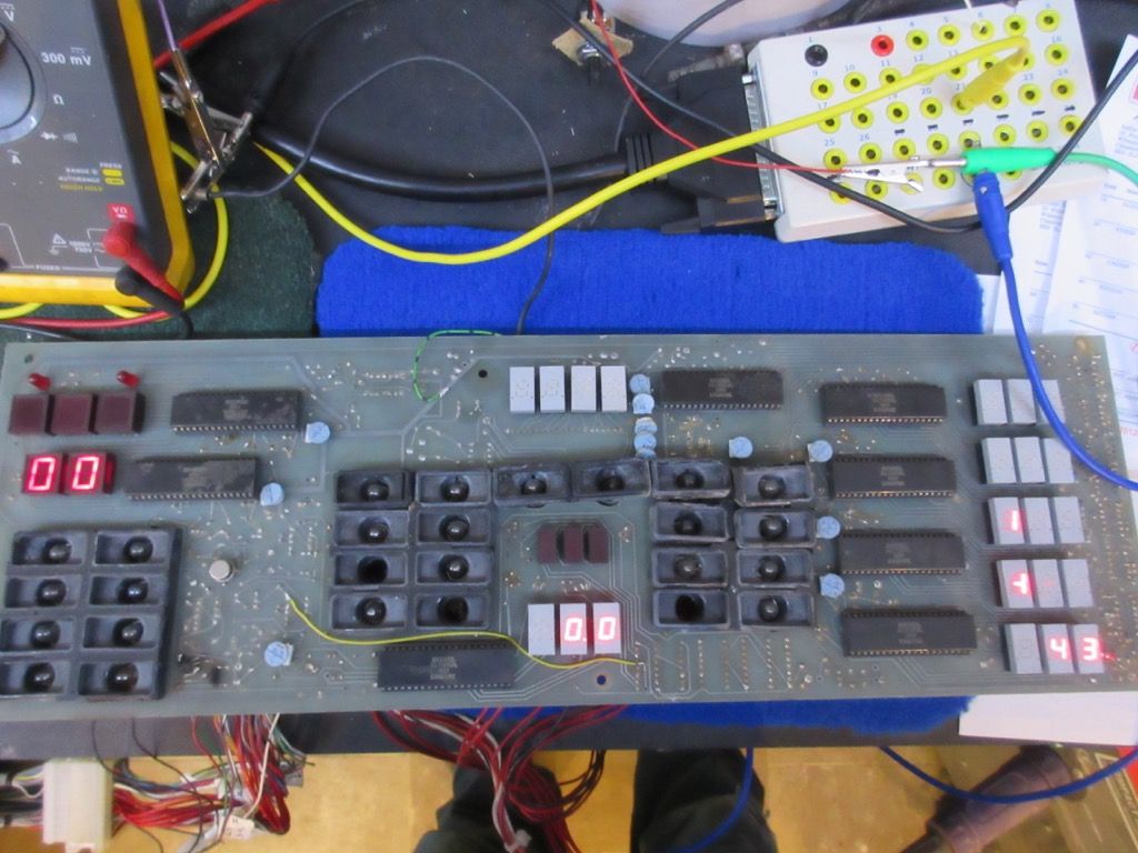
Well, sort of. When I say 'works' actually I mean 'lights up'.
I won't bore you with every detail of the repairs but as I said earlier, chips soldered directly to the board slows things down.
First the old one has to be removed without damaging the board, and the holes solder-free.
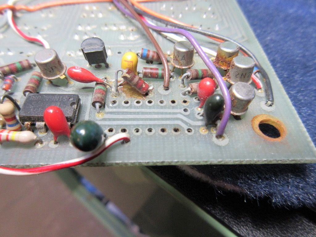
Then a socket can be soldered in:
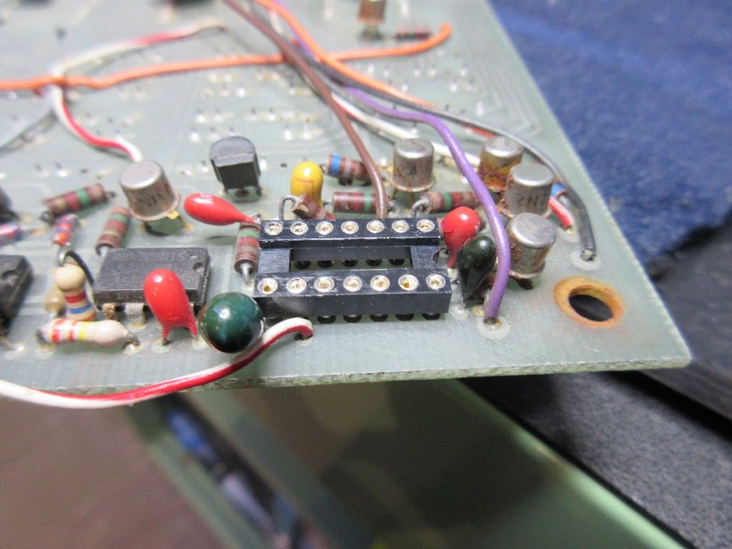
And then (after some Contralube contact grease on the socket connections) the replacement chip can be fitted.
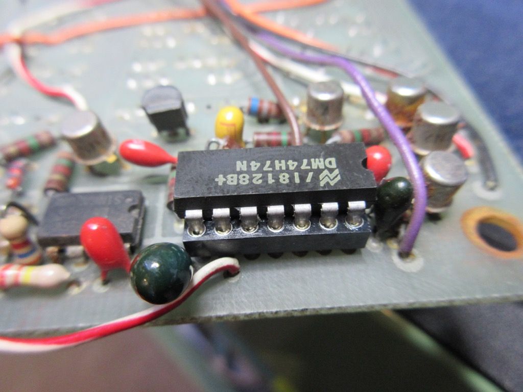
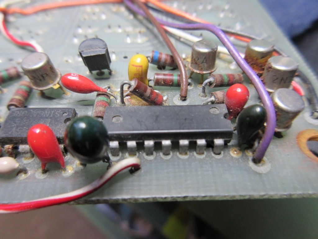
This is not helped when the component is obsolete, which a number of them are. It is also not helped when the chip has board interconnect wires running over the top of it like this one:
These are short wires running from one part of the board to another, and are not long enough to move out of the way. Here is the solution:
Fortunately eBay has been a great help sourcing obsolete components.
Now I have made up the part of the loom which connects the binnacles to the instrument panel.
And I can continue to test and repair.
 |
|
| Back to top |
|
|
Christoph
Joined: 19 Feb 2011
Posts: 51
|
| Posted: Wed Dec 23, 2015 10:53 pm Post subject: |
|
|
WS should follow Jonathan´s example!
_________________
Christoph |
|
| Back to top |
|
|
Mitrovic

Joined: 19 Nov 2007
Posts: 627
|
| Posted: Thu Dec 24, 2015 7:36 am Post subject: |
|
|
| That is unreal! Who are you? A wizard? |
|
| Back to top |
|
|
Lagondanet
Administrator
Joined: 03 Jan 2007
Posts: 3108
Location: UK
|
| Posted: Thu Dec 24, 2015 11:33 am Post subject: |
|
|
I doubt WS could do it.
By 004 do you mean this might have come of 13004 the turbo car? |
|
| Back to top |
|
|
jonc
Joined: 21 Sep 2010
Posts: 584
Location: Cheshire, UK
|
| Posted: Thu Dec 24, 2015 12:13 pm Post subject: |
|
|
No.
These are serial numbers from manufacture of the board. 004 would be the forth one of these boards made. I have no idea which car it would have been in, but it would be an early one.
For the production ones, they have a serial number from Javelina, plus AML then wrote in pen the chassis number. This one has no chassis number on it, but then none of the rest of the car does either. In other words - before production line build. |
|
| Back to top |
|
|
|
|
You cannot post new topics in this forum
You cannot reply to topics in this forum
You cannot edit your posts in this forum
You cannot delete your posts in this forum
You cannot vote in polls in this forum
|
|


